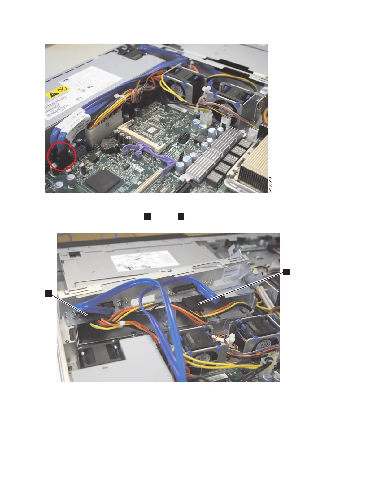
9. Remove power connectors P1
1
and P6
2
, as shown in Figure 277.
10. Remove the cables from the Front USB and the Front panel sockets.
11. Remove the cable from the IDE connector, which is identified in Figure 278 on page 278.
Figure 276. SAN Volume Controller 2145-8A4 SATA cable connectors
1
2
svc00482
Figure 277. SAN Volume Controller 2145-8A4 power supply connectors
Chapter 2. Removing and replacing parts 277
 Loading...