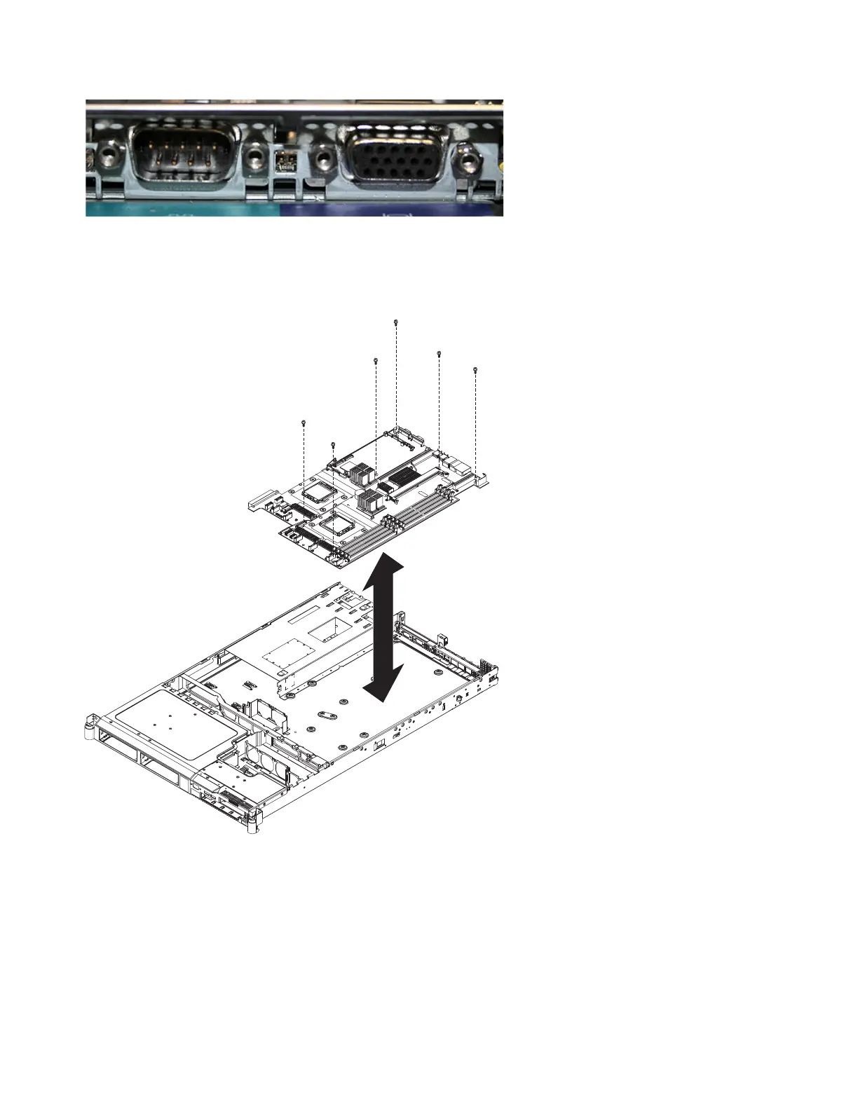
19. Remove the six screws on the system board, as shown in Figure 288, that secure the system board to
the chassis.
20. Lift up the front edge of the system board slightly so that it disengages from the locator pin. Slide
the system board slightly toward the front of the node so that the I/O ports are free of the chassis.
21. Lift up the left side of the system board.
22. Lift up the rest of the system board and carefully remove it from the node, being careful not to
disturb any surrounding components.
svc00411
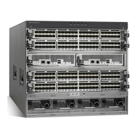
Figure 287. Serial and video ports on the SAN Volume Controller 2145-8G4
Figure 288. The placement of the screws that secure the SAN Volume Controller 2145-8G4 system board
286 IBM SAN Volume Controller Hardware Maintenance Guide
 Loading...