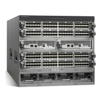
5. Push the back rail bracket 1 (Figure 62) toward the front of the rail until it stops. The rail is now at
its shortest adjustment.
1 Latch-lever
2 Latch-lock
3 Back rail bracket
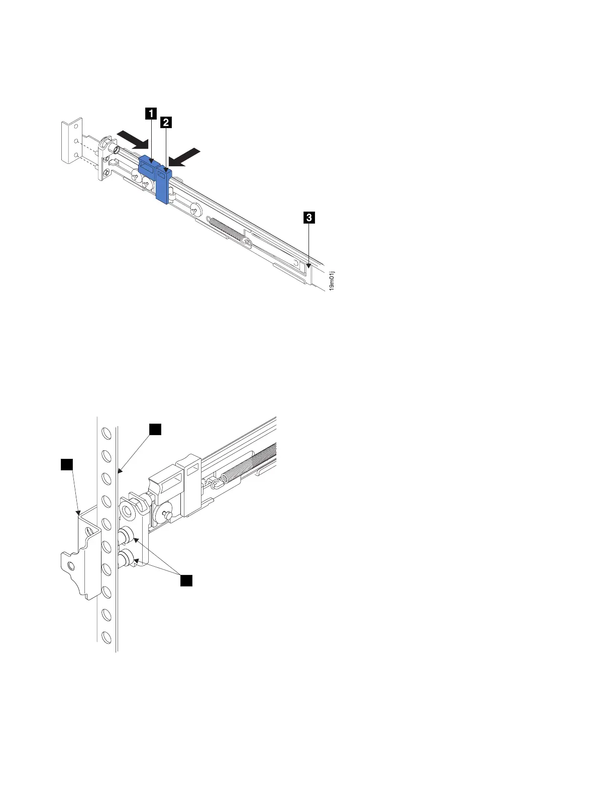
6. Place the front end of the left rail in the rack cabinet. Align the top of the front bracket 1
(Figure 63) with the required EIA marking that is on the rack.
1 Front bracket
2 Rack-mounting flange
3 Locating pins
Figure 62. Opening the back latch-lock carrier assembly
1
2
3
Figure 63. Installing the front end of the rail
76 IBM SAN Volume Controller Hardware Maintenance Guide
 Loading...