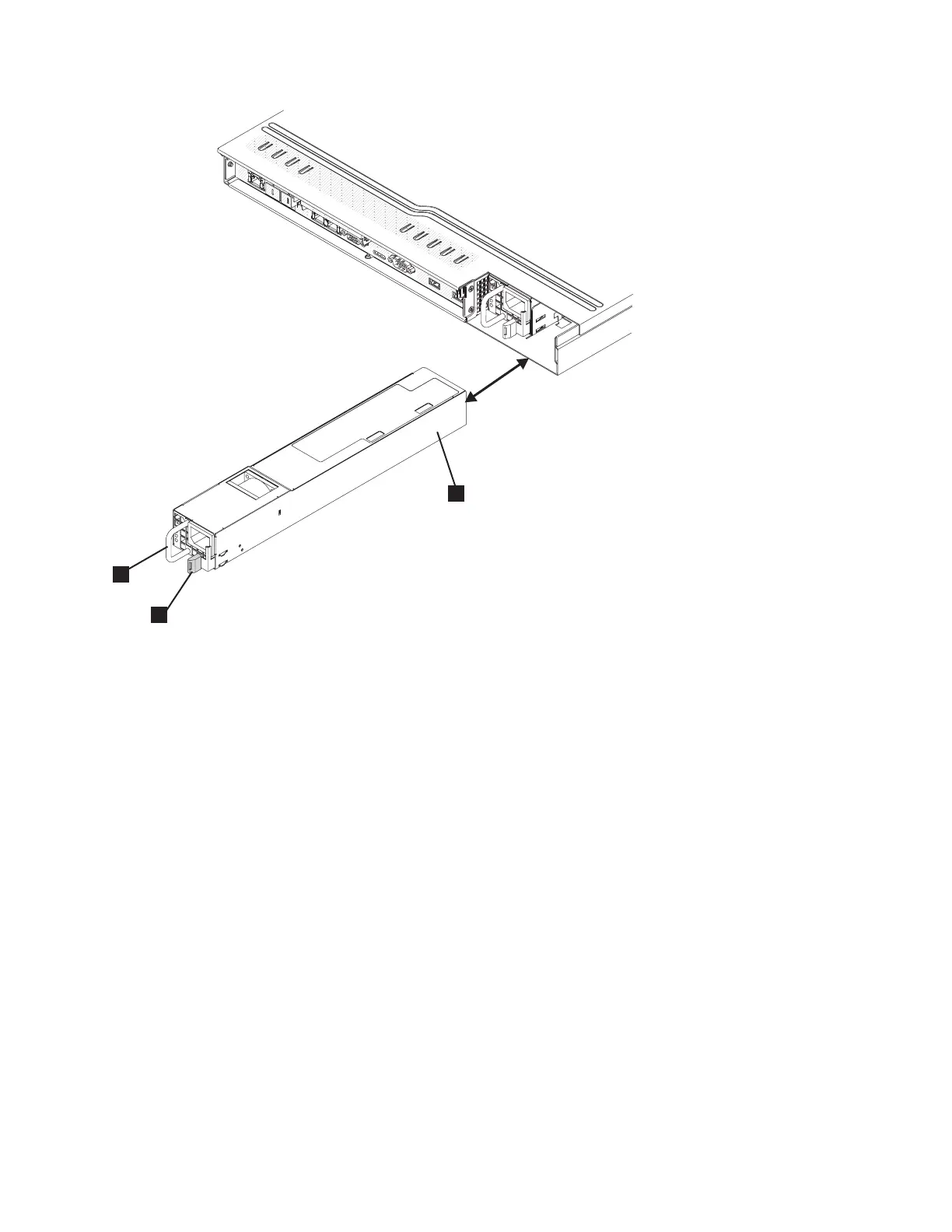
1 Power supply
2 Power-supply release tab
3 Power-supply handle
3. Attach the cable-retention bracket to the power cord from the 2145 UPS-1U and connect the cord to
the power-cord connector on the power supply, as described in “Replacing the SAN Volume
Controller 2145-CG8 or 2145-CF8 cable-retention brackets” on page 39.
4. If necessary, turn on the node.
5. To the left of the power-cord connector on each power supply, verify that the ac power LED, as
shown by 1 in Figure 156 on page 166, and the dc power LED (2) are lit.
The green power LEDs indicate that the power supply is operating correctly. A power-supply error is
indicated by the amber power-supply error LED (3).
svc00543
2
1
3
Figure 155. SAN Volume Controller 2145-CG8 or 2145-CF8 power supply
Chapter 2. Removing and replacing parts 165
 Loading...