5. Replace the top cover. See “Replacing the top cover” on page 81.
6. Place the node in the rack. See “Replacing the SAN Volume Controller in a rack” on page 55.
7. Reconnect the Fibre Channel and Ethernet cables. Ensure that you replace the Fibre Channel and
Ethernet cables in the same ports from which they were removed.
8. Turn on the node.
Replacing the SAN Volume Controller 2145-8F4 or SAN Volume Controller
2145-8F2 power backplane
The SAN Volume Controller 2145-8F4 or SAN Volume Controller 2145-8F2 power backplane might have
to be replaced.
Take precautions to avoid damage from static electricity. Wear an anti-static wrist strap and use a
static-protected mat or surface. For more information, see “Handling static-sensitive devices” on page xx.
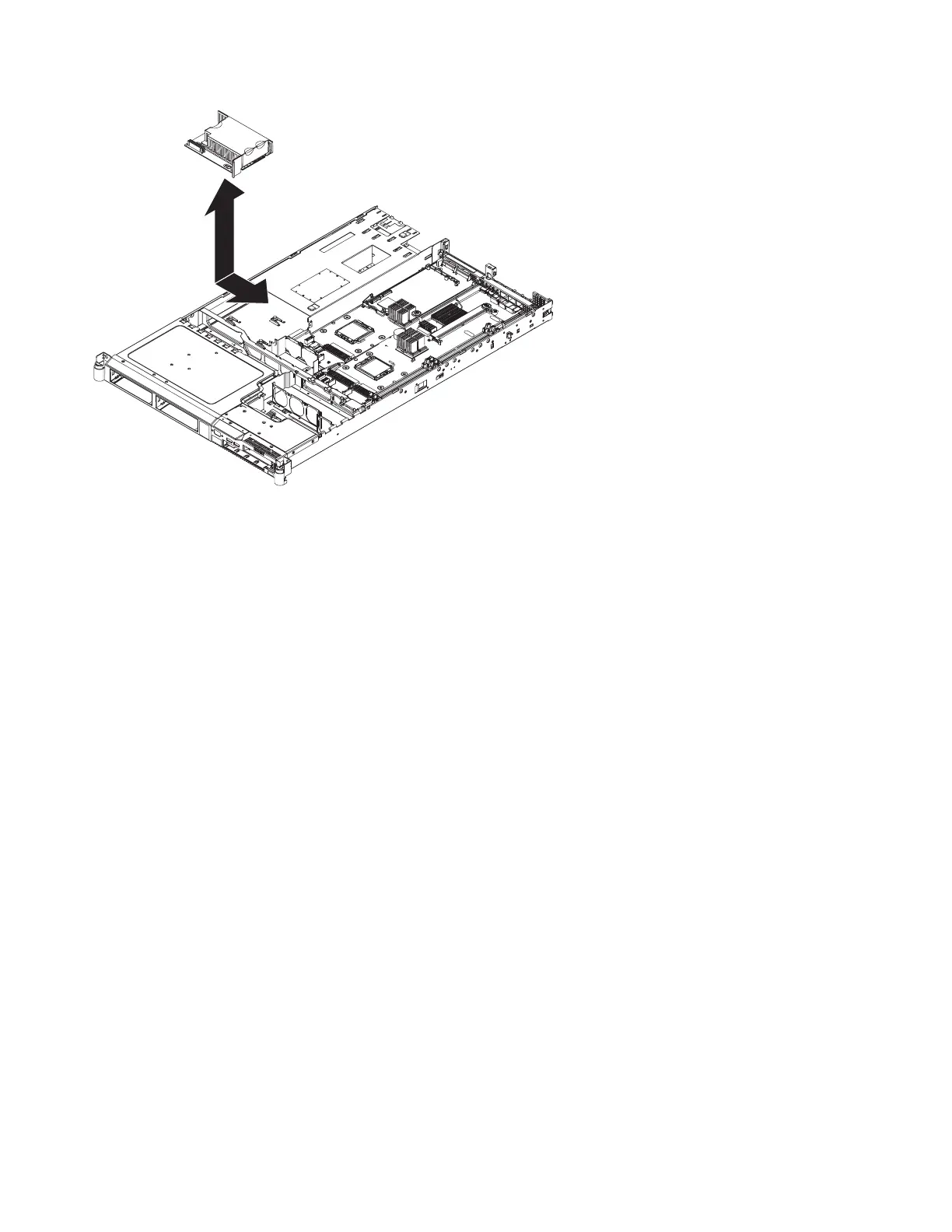
Perform the following steps to replace the power backplane:
1. Lower the power backplane into position on the SAN Volume Controller 2145-8F4 or SAN Volume
Controller 2145-8F2 and slide it to the right to connect it to the system board. See Figure 167 on page
175.
svc00286
Figure 166. SAN Volume Controller 2145-8G4 power backplane
174 IBM SAN Volume Controller Hardware Maintenance Guide
 Loading...