1 Operator-information panel
2 Release tab
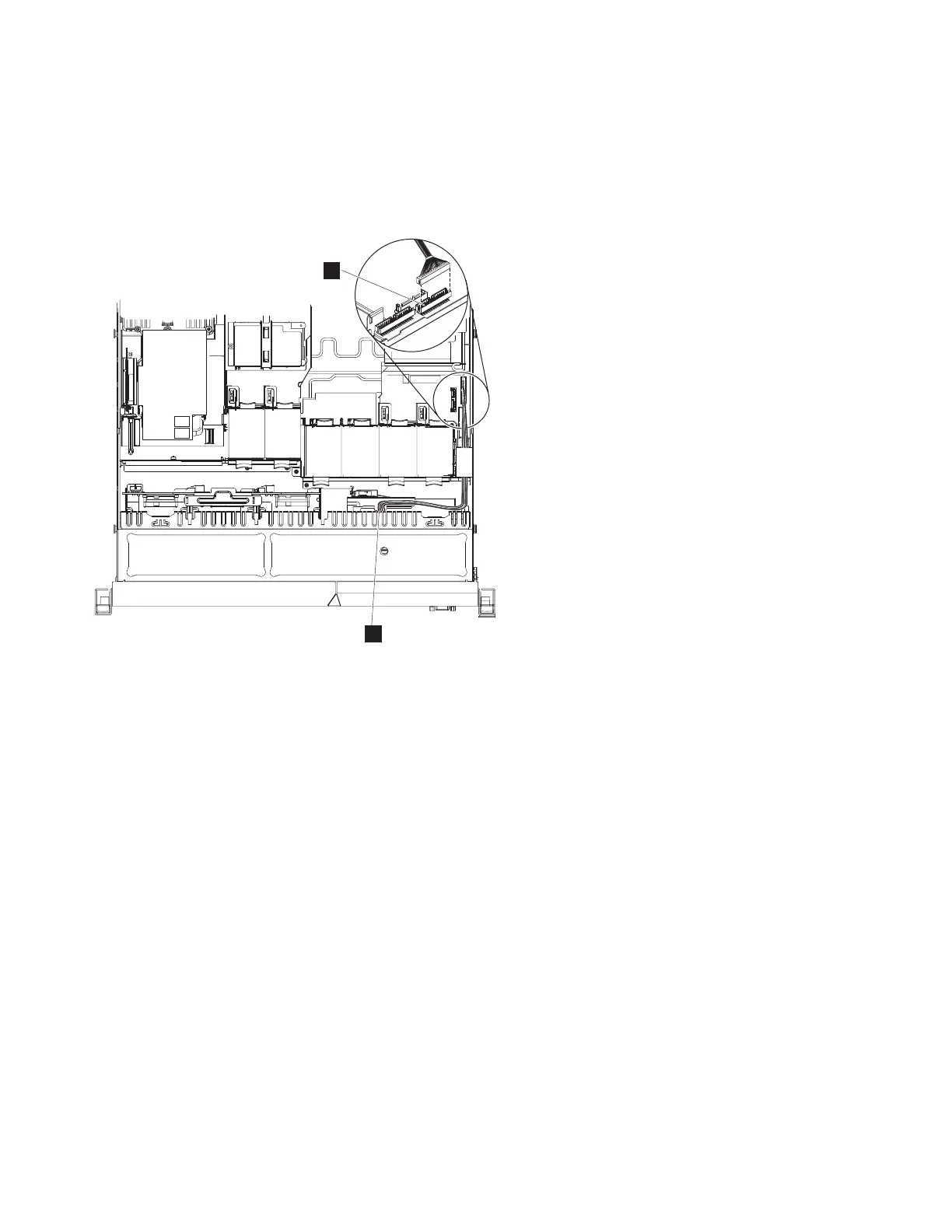
The following illustration shows the cable routing for the operator-information panel:
Note: The operation information panel cable should go in above the Video/USB cable in the node.
1 Operator-information panel connector
2 Operator-information panel cable
4. Replace the top cover. See “Replacing the top cover” on page 81.
5. If you removed the node from the rack, replace the node in the rack, as described in “Replacing the
SAN Volume Controller in a rack” on page 55.
6. If you removed any Fibre Channel or Ethernet cables, use the labels you placed on each cable to
replace all Fibre Channel and Ethernet cables in the same ports from which they were removed.
7. If you removed the power cords, replace the power cords and the cable-retention brackets, as
described in “Replacing the cable-retention bracket” on page 39.
8. Lift the locking levers (1 in Figure 224 on page 227) on the slide rails and push the server 2 all
the way into the rack until it clicks into place.
1
2
Figure 223. Connecting the SAN Volume Controller 2145-CG8 or 2145-CF8 operator-information panel cable
226 IBM SAN Volume Controller Hardware Maintenance Guide
|
|
|
|
|
|
|
|
|
|
|
 Loading...