Replacing the redundant ac-power switch
Use this topic when you need to replace a redundant ac-power switch.
The redundant ac-power switch FRU assembly includes the redundant ac-power switch and the input
power cables. They should all be replaced together.
These instructions assume that a redundant ac-power switch has been removed and the one or two nodes
that were connected to it are powered off.
To replace a redundant ac-power switch, complete the following steps:
1. Attach each of the two mounting plates to the redundant ac-power switch using three M3 Torx T8
head screws. Position the mounting face, as shown in Figure 303, on the side of the redundant
ac-power switch that contains the output power sockets.
2. Using the labels provided, label each end of the two redundant ac-power switch input power cables.
Unless the configuration is changing, the labels are the same as those on the cables removed with
the old redundant ac-power switch. Label the rack power distribution end “Power source <name>,
outlet <id>” to redundant ac-power switch <location> <MAIN | BACKUP> input. For example: “Power
source D2, outlet 4 to redundant ac-power switch pos 7 MAIN input”.
3. Label the redundant ac-power switch end“ redundant ac-power switch <location> <MAIN | BACKUP>
input from Power source <name>, outlet <id>”.
4. Connect the input power cables to the redundant ac-power switch. You want to connect the cables
now, because it is difficult to access the input power sockets on the redundant ac-power switch
when it is installed in a rack.
5. Connect the main input power cable to the redundant ac-power switch.
6. Connect the backup input power cable to the redundant ac-power switch.
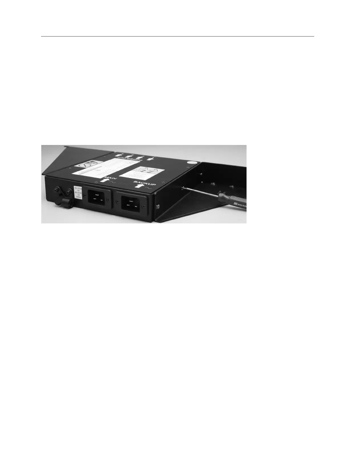
7. Secure both the redundant ac-power switch input cables, as shown in Figure 304 on page 304, using
the clips of the redundant ac-power switch.
svc00294
Figure 303. Attaching the mounting plates
Chapter 2. Removing and replacing parts 303
 Loading...