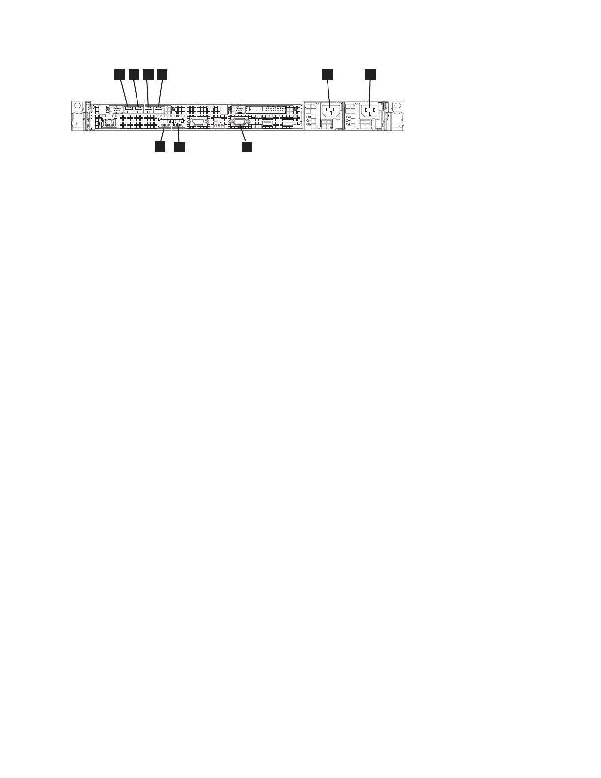
1 Fibre Channel port 1
2 Fibre Channel port 2
3 Fibre Channel port 3
4 Fibre Channel port 4
5 Power connector 1
6 Power connector 2
7 Serial port for UPS communications (RS232)
8 Ethernet port 2
9 Ethernet port 1
This service action requires you to remove the cover and:
v Turn the node off.
v Disconnect the power cables.
v Disconnect the data cables.
To remove the SAN Volume Controller 2145-CG8 or 2145-CF8 Fibre Channel adapter assembly, perform
the following steps:
1. Read the safety information to which “Preparing to remove and replace parts” on page 26 refers.
2. Follow the procedure in MAP 5350 in the IBM System Storage SAN Volume Controller Troubleshooting
Guide to verify that the node data is mirrored and synchronized, and that there are no dependent
volumes before turning off the node.
3. Slide the node out on its slide rails to the fully extended position.
4. When the node is completely turned off, remove the cable-retention brackets and disconnect the
power cables, as described in “Removing the cable-retention bracket” on page 34.
5. To make sure that you can replace all cables in the same ports from which they were removed, label
the port position of each Fibre Channel and Ethernet cable; then remove all cables from the back of
the node.
6. Optional: Remove the node from the rack and place it on a flat, static-protective surface. See
“Removing the SAN Volume Controller from a rack” on page 46.
You can perform most service actions when the node is fully extended from the rack on its slide
rails. If the location of the node in the rack is too high or too low to work comfortably, you can
remove the node from the rack.
7. Remove the top cover. See “Removing the top cover” on page 77.
8. Remove all small form-factor pluggable (SFP) transceivers before removing the adapter, as described
in “Removing and replacing the Fibre Channel SFP transceiver on a SAN Volume Controller node”
on page 177.
9. Remove the two M3 screws that attach the adapter assembly to the back rail.
The Fibre Channel adapter assembly and the high-speed SAS adapter assembly each attach to the
back rail with two screws, as shown in the partial view of the rail with the Fibre Channel adapter
4
3
1 2 65
7
9
svc_00219_cf8
8
Figure 169. Connectors on the rear of the SAN Volume Controller 2145-CG8 or 2145-CF8
Chapter 2. Removing and replacing parts 179
|
|
 Loading...