d. Use a clean area of the cleaning pad to wipe the thermal grease from the microprocessor; then,
dispose of the cleaning pad after all of the thermal grease is removed.
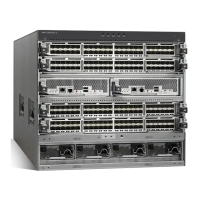
e. Use the thermal-grease syringe to place 9 uniformly spaced dots of 0.02 mL each on the top of
the microprocessor, as shown in Figure 263. The outermost dots must be within approximately 5
mm of the edge of the microprocessor to ensure uniform distribution of the grease.
1 Microprocessor
2 0.02 mL of thermal grease
Note: If properly applied, approximately half of the grease remains in the syringe when you are
done.
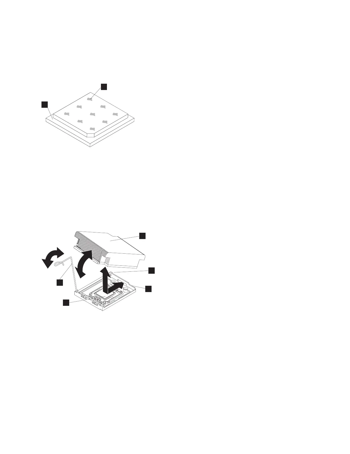
8. Align the heat sink on top of the microprocessor, as shown in Figure 264.
1 Microprocessor
2 Heat-sink release lever
3 Heat sink
4 Lock tab
5 Retainer bracket
9. Lower the rear flange of the heat sink into the opening in the retainer bracket (5) and press down
firmly on the front of the heat sink until it is seated securely.
10. Rotate the heat-sink release lever (2) to the closed position and hook the lever underneath the lock
tab (4).
11. Replace the top cover. See “Replacing the top cover” on page 81.
2
1
Figure 263. Applying thermal grease to the SAN Volume Controller 2145-CG8 or 2145-CF8 microprocessor
1
2
3
4
5
Figure 264. Installing the heat sink on the SAN Volume Controller 2145-CG8 or 2145-CF8 microprocessor
Chapter 2. Removing and replacing parts 263
|
|
|
|
|
|
|
|
|
|
|
 Loading...