1
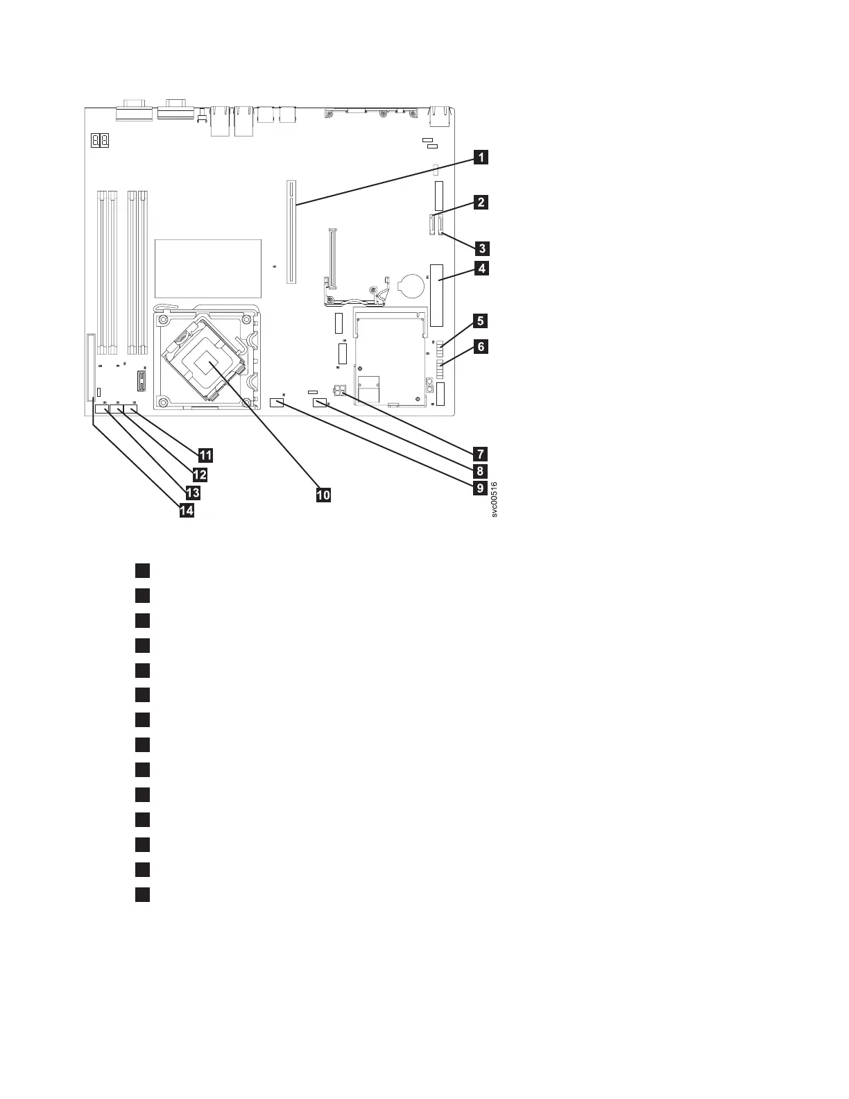
PCI express riser card connector
2
SATA 2 connector
3
SATA 0 connector
4
Power connector P1
5
Front USB connector
6
Operator-information panel connector
7
Power connector P6
8
Fan 5 connector
9
Fan 4 connector
10
Microprocessor connector
11
Fan 3 connector
12
Fan 2 connector
13
Fan 1 connector
14
IDE connector
8. Disconnect and remove both SATA disk cables from sockets SATA 0 and SATA from the system
board, as shown in Figure 276 on page 277.
Figure 275. Connectors that are used on the SAN Volume Controller 2145-8A4 system board
276 IBM SAN Volume Controller Hardware Maintenance Guide
 Loading...