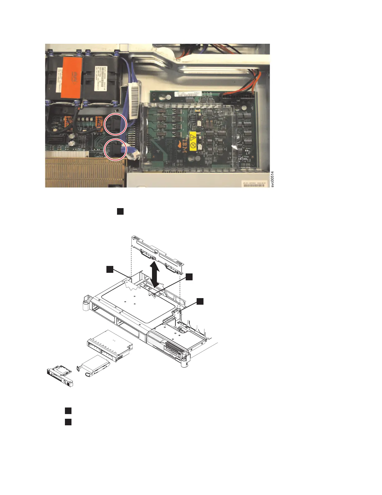
9. Press the locking tab
1
, which is shown in Figure 120, and lift the backplane out of the node
slightly. Disconnect the power cable and remove the backplane.
1
Locking tab
2
Mounting channel
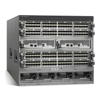
Figure 119. The SAN Volume Controller 2145-8G4 disk-drive backplane connectors
1
svc00306
2
2
Figure 120. The SAN Volume Controller 2145-8G4 SATA disk drive and backplane
Chapter 2. Removing and replacing parts 133
 Loading...