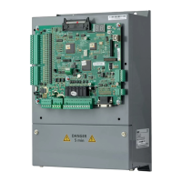
User manual of EC160 elevator intelligent integrated machine Running at slow speed
142
Chapter 7 Running at slow speed
7.1 Inspection before power on
7.1.1 Machinery assembly, inspection and confirmation
¾ Bracket, rail, traction machine, car, rope, control cabinet and governor are installed
according to the standards.
¾ Confirm all the assembly of the safety circuit, such as four emergency stop buttons of engine
room/car/car top/pit, phase sequence, governor switch, up/down limit switch, hydraulic
buffer switch, rope broken switch, safety plier switch and safety window switch, are well
installed and in the normal working state.
¾ Check the installation of all hall and car doors to ensure valid action and normal working
state.
¾ Remove all scaffolds and other obstacles in the hoistway.
7.1.2 Electrical assembly, inspection and confirmation
1. Check the connection of:
(1) Three-phase wires between the power supply cabinet and the control cabinet
(2) The connection between the braking coil of the master and the control cabinet.
(3) The connection between U1, V1 and W1 of the control cabinet and the three-phase wires of the
master motor.
(4) The connection between the master encoder and the control cabinet.
(5) The safety circuit
(6) The door lock circuit
(7) The car top connection
(8) Logic of the inspection circuit
(9) Power supply and signal connection of the door operator
(10) CAN communication circuit connection of the car
(11) RS-485 communication circuit connection of the hoistway
2. Connect the communication cables of the hoistway and car to the control cabinet
(1) Confirm the connection of the terminal resistor on the DC-03F board in the car
(2) Ensure the connection of the terminal resistor on the DC-03F board in the bottom hoistway
module
(3) Connect the hoistway communication module, the resistance is about 60Ω.
(4) Connect the car communication module, the resistance is about 60Ω.
3. Check the resistance of three phase of the motor

 Loading...