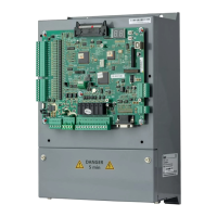
User manual of EC160 elevator intelligent integrated machine Installation and wiring
39
z In the system, EMS and EMI of inverter coexist. Decrease the EMI of inverter can increase its
EMS ability.
4.6.3 EMC installation guideline
In order to ensure all electric devices in the same system to work smoothly, this section, based on
EMC features of inverter, introduces EMC installation process in several aspects of application (noise
control, site wiring, grounding, leakage current and power supply filter). The good effect of EMC will
depend on the good effect of all of these five aspects.
4.6.3.1 Noise control
All the connections to the control terminals must use shielded wire. And the shield layer of the wire
must ground near the wire entrance of inverter. The ground mode is 360 degree annular connection
formed by cable clips. It is strictly prohibitive to connect the twisted shielding layer to the ground of
inverter, which greatly decreases or loses the shielding effect.
Connect inverter and motor with the shielded wire or the separated cable tray. One side of shield
layer of shielded wire or metal cover of separated cable tray should connect to ground, and the other
side should connect to the motor cover. Installing an EMC filter can reduce the electromagnetic noise
greatly.
4.6.3.2 Site wiring
Power supply wiring: the power should be separated supplied from electrical transformer. Normally it
is 5 core wires, three of which are fire wires, one of which is the neutral wire, and one of which is the
ground wire. It is strictly prohibitive to use the same line to be both the neutral wire and the ground
wire.
Device categorization: there are different electric devices contained in one control cabinet, such as
inverter, filter and instrument etc, which have different ability of emitting and withstanding
electromagnetic noise. Therefore, it needs to categorize these devices into strong noise device and
noise sensitive device. The same kind of device should be placed in the same area, and the distance
between devices of different category should be more than 20cm.
Wire arrangement inside the control cabinet: there are signal wire (weak current) and power cable
(strong current) in one cabinet. For the inverter, the power cables are categorized into input cable and
output cable. Signal wires can be easily disturbed by power cables to make the equipment
malfunction. Therefore when wiring, signal cables and power cables should be arranged in different
area. It is strictly prohibitive to arrange them in parallel or interlacement at a close distance (less than
20cm) or tie them together. If the signal wires have to cross the power cables, they should be
arranged in 90 angles. Power input and output cables should not be arranged in interlacement or tied
together, especially when installed the EMC filter. Otherwise the distributed capacitances of its input

 Loading...