User manual of EC160 elevator intelligent integrated machine Complete product description
165
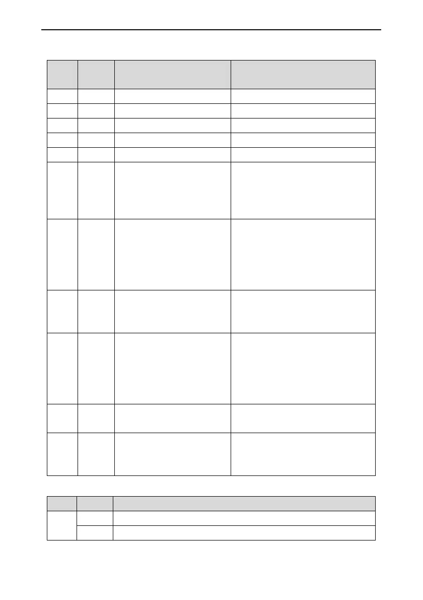
9.1.2 Interface definition
Serial
No.
Pin Code Terminal definition
1 P1 4-core terminal Download port of J-link
2 P2 CANH1, CANL1, 24-, 24+ CAN communication interface
3 P3 CANH2, CANL2, 24-, 24+ CAN communication interface
4 P4 24V+, 24V-, B, A RS485 communication interface
5 P5 8-core terminal Download port of serial software
6 P6
RSE, RDCL, RDOL, CMM;
SE, DCL, DL, DOL, CMM;
Rear door beam, close/open signal of
rear door
Front door beam, close/open signal of
front door
7 P7
24V, AI, CMM;
BK1, OL, LL, FL, CMM;
24V and CMM provide DC24 power; AI
and CMM are 0~10V input; BK1 is the
spare input; OL is the overload input; LL
is the light load input and FL is the full
load input
8 P8 KLS1, CM1, KSL2;
KLS1 and CM1 are the NC contact of
energy control; KLS2 and CM1 are the
NO contact of energy control
9 P9
CHM, CM2, DO, DC, CM3,
RDO, RDC, CM4;
CHM and CM2 are the arrival control;
DO, DC and CM3 are the front door
open/close control; RDO, RDC and
CM4 are the rear door open/close
control
10 CN1 DB9 (female)
CN1 port connects the internal
command board
11 CN2 DB9 (female)
CN1 port connects the internal
command board (for the command
button of the rear door)
9.1.3 DIP instruction
No. Bit Function
J1
1 Switch to “ON” when use external protocol. Switch to “OFF” in factory.
2 Switch to “ON” and the terminal resistor is valid. Switch to “OFF” in factory.
 Loading...