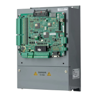
User manual of EC160 elevator intelligent integrated machine Complete product description
180
CG2 Output Grounding terminal of CAN2
Not grounded
generally
NC Output Not connected
9.4.5.3 Definition of I/O terminal
Serial
No.
Pin I/O Definition
Corresponding
LED
P1
COM Input
1, 2, 3 and 4 pins input
common terminal
—
1 Input Not defined L4
2 Input Not defined L3
3 Input Not defined L2
4 Input Not defined L1
9.4.6 Definition of jumper terminal
Serial
No.
Definition of pin Remarks
J1
Short circuit the connector in serial download software
mode
Not short circuit
J2
Short circuit pin between group control board and CAN
communication terminal resistance defined on EC160-I/O
board; in short circuit, resistance about 120Ω, if not,
communication resistance open circuit
Default short circuit
J3
Short circuit pin between group control board and CAN
communication terminal resistance; in short circuit,
resistance about 120Ω, if not, communication resistance
open circuit
Default short circuit;
on site, 2 farthest J3
need short circuit
while other J3
unnecessary.
9.4.7 Instruction of LED
Name Instruction
LED1
When no communication is at CAN1, LED1 will be on at the interval of 0.5s; when
communication at CAN1 is normal, LED1 will flicker continuously.
LED2
When no communication is at CAN1, LED2 will be off; when communication at
CAN1 is normal, LED2 will flicker continuously.
LED3
When no communication is at CAN2, group number is 3 (No.1 elevator) and LED3
is on at the interval of 0.5s; when communication at CAN2 is normal, group number

 Loading...