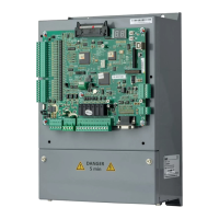
User manual of EC160 elevator intelligent integrated machine Running at slow speed
144
(2) The connection of the encoder is brought into the control cabinet.
(3) If the connection cable is not long enough, it is necessary to lengthen the cables and the cables
should be shield cables. It is recommended to weld the connection wires and the wire should be
isolated from each other with the metal shield.
(4) Connect according to the color of the connection diagram and the encoder.
(5) The shield cables are connected to the grounding terminal in the control cabinet.
(6) The cable of the encoder should be arranged in the metal hose to the control cabinet. The ends
should be connected with proper techniques and the end of the metal hose in the control cabinet
should be grounded.
If the shield cable of the encoder is grounded , then it can not be connected, but ensure the cable
is not connected with any electrical terminal or grounding chassis.
7.2 Inspection after power on
1. Following steps is needed after the first inspection:
(1) Ensure all the switches and fuses are off
(2) Ensure the inspection/normal switch is in the right position, the emergence-stop switch is off.
(3) Ensure the inspection switch on and in the car is in the right position.
(4) Ensure there is nobody in the hoistway, car, on the top of the car and at the bottom of the
hoistway and the elevator can run safely.
(5) Ensure the working outside the hoistway does not affect the running of the elevator.
2. Check the site bus voltage, the 3-phase voltage is 380±7%VAC and the phase bias is no more
than 15VAC. The single voltage between each phase and the N wire is 220±7%VAC. If N line and
PE is connected, then the voltage between N-PE is no more than 30VAC.
3. Ensure the wire specification and the total switching capacity should reach the total
requirements of the diagram.
4. Power on debugging if all inspections are correct.
5. Inspection after power on:
(1) Switch on the main power switch and check the phase sequence relay, if the green light is on,
the phase is normal, otherwise, switch off the power and exchange any two-phase lines.
(2) Check the fault immediately if fault occurs.
A. Check the voltage between 24V+ and 24V- is 24.3V±0.3V.
B. Check the relay in the control cabinet
Relay name Close/release
Phase sequence relay Action
(3) Input the password on the manual controller and enter into the parameters menu. After

 Loading...