User manual of EC160 elevator intelligent integrated machine Installation and wiring
27
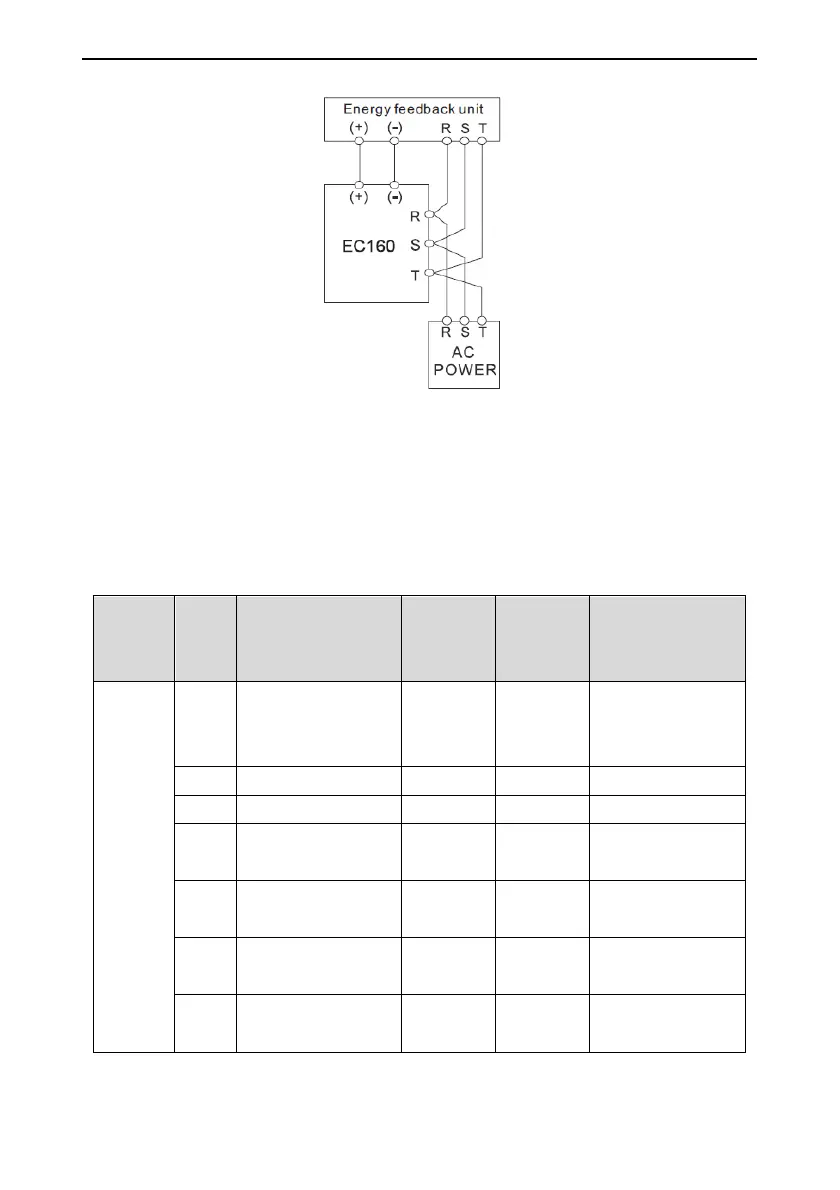
Figure 4-6 Connection diagram of energy feedback unit
4.2.7 Connection of PE terminal
The PE terminal needs to be grounded with proper techniques to avoid electric shock and fire. The
resistance is less than 10Ω. The grounding must be single-point to avoid a circuit.
4.3 Terminals of control circuit
4.3.1 Definition of terminals
Plug-in
No.
Pin
No.
Terminal definition Code
LED
indicator
code
Remarks
CN3
terminals
1-16
S1
Up door area (rear
door opening
detection)
SUDZ LED4 Default NO input
S2 Middle door area SMDZ LED5 Default NO input
S3 Down door area SDDZ LED6 Default NO input
S4
Contact detection of
safety contactor
KASF LED7 Default NO input
S5
Contact detection of
door lock contactor
KDL
LED8
Default NO input
S6
Contact detection of
drive output contactor
KM1 LED9 Default NC input
S7
Contact detection of
brake contactor
KBK
LED10
Default NC input
 Loading...