RL78/G1H CHAPTER 6 CLOCK GENERATOR
R01UH0575EJ0120 Rev. 1.20 Page 137 of 920
Dec 22, 2016
6.6.6 Time required for switchover of CPU clock and main system clock
By setting bits 4 and 6 (MCM0, CSS) of the system clock control register (CKC), the CPU clock can be switched
(between the main system clock and the subsystem clock), and main system clock can be switched (between the
high-speed on-chip oscillator clock and the high-speed system clock).
The actual switchover operation is not performed immediately after rewriting to the CKC register; operation
continues on the pre-switchover clock for several clocks (see Tables 6 - 10 to 6 - 12).
Whether the CPU is operating on the main system clock or the subsystem clock can be ascertained using bit 7
(CLS) of the CKC register. Whether the main system clock is operating on the high-speed system clock or high-
speed on-chip oscillator clock can be ascertained using bit 5 (MCS) of the CKC register.
When the CPU clock is switched, the peripheral hardware clock is also switched.
Remark 1. The number of clocks listed in Tables 6 - 11 and 6 - 12 is the number of CPU clocks before switchover.
Remark 2. Calculate the number of clocks in Tables 6 - 11 and 6 - 12 by rounding up the number after the decimal position.
Example When switching the main system clock from the high-speed system clock to the high-speed on-chip oscillator
clock (@ oscillation with f
IH = 8 MHz, fMX = 10 MHz)
2 f
MX/fIH = 2 (10/8) = 2.5 → 3 clocks
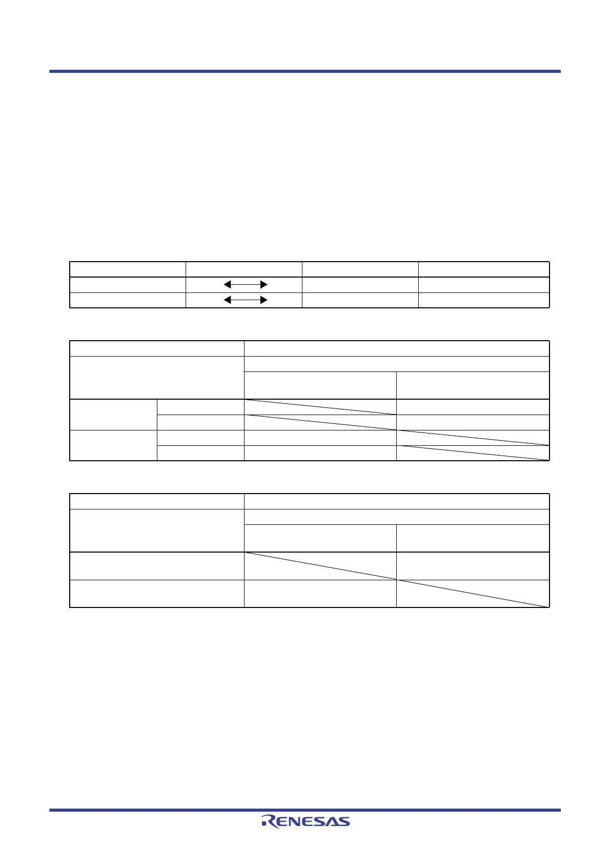
Table 6 - 10 Maximum Time Required for Main System Clock Switchover
Clock A Switching directions Clock B Remark
f
IH fMX See Table 6 - 11
fMAIN fSUB See Table 6 - 12
Table 6 - 11 Maximum Number of Clocks Required for fIH ↔ fMX
Set Value Before Switchover Set Value After Switchover
MCM0 MCM0
0
(f
MAIN = fIH)
1
(fMAIN = fMX)
0
(f
MAIN = fIH)
f
MX ≥ fIH 2 clock
f
MX < fIH 2 fIH/fMX clock
1
(f
MAIN = fIH)
f
MX ≥ fIH 2 fMX/fIH clock
f
MX < fIH 2 clock
Table 6 - 12 Maximum Number of Clocks Required for fMAIN ↔ fSUB
Set Value Before Switchover Set Value After Switchover
CSS CSS
0
(f
CLK = fMAIN)
1
(fCLK = fSUB)
0
(f
CLK = fMAIN)
1 + 2 f
MAIN/fSUB clock
1
(f
CLK = fSUB)
3 clock
 Loading...


