RL78/G1H CHAPTER 6 CLOCK GENERATOR
R01UH0575EJ0120 Rev. 1.20 Page 126 of 920
Dec 22, 2016
6.6.2 Example of setting X1 oscillation clock
After a reset release, the CPU/peripheral hardware clock (fCLK) always starts operating with the high-speed on-
chip oscillator clock. To subsequently change the clock to the X1 oscillation clock, set the oscillator and start
oscillation by using the oscillation stabilization time select register (OSTS), clock operation mode control register
(CMC), and clock operation status control register (CSC) and wait for oscillation to stabilize by using the
oscillation stabilization time counter status register (OSTC). After the oscillation stabilizes, set the X1 oscillation
clock to f
CLK by using the system clock control register (CKC).
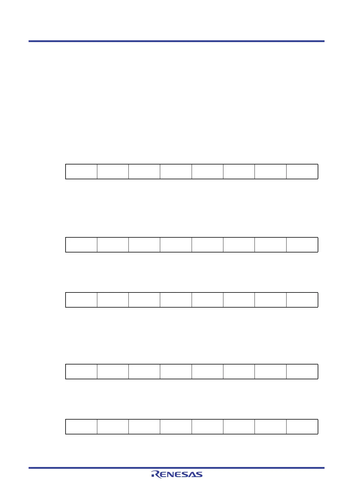
[Register settings] Set the register in the order of <1> to <5> below.
<1> Set (1) the OSCSEL bit of the CMC register, except for the cases where the fx is equal to or more than 10 MHz, in
such cases set (1) the AMPH bit, to operate the X1 oscillator.
<2> Using the OSTS register, select the oscillation stabilization time of the X1 oscillator at releasing of the STOP
mode.
Example: Setting values when a wait of at least 102 μs is set based on a 10 MHz resonator.
<3> Clear (0) the MSTOP bit of the CSC register to start oscillating the X1 oscillator.
<4> Use the OSTC register to wait for oscillation of the X1 oscillator to stabilize.
Example: Wait until the bits reach the following values when a wait of at least 102 μs is set based on a 10 MHz
resonator.
<5> Use the MCM0 bit of the CKC register to specify the X1 oscillation clock as the CPU/peripheral hardware clock.
76543210
CMC
EXCLK
0
OSCSEL
1
EXCLKS
0
OSCSELS
00
AMPHS1
0
AMPHS0
0
AMPH
0/1
76543210
OSTS
00000
OSTS2
0
OSTS1
1
OSTS0
0
76543210
CSC
MSTOP
0
XTSTOP
100000
HIOSTOP
0
76543210
OSTC
MOST8
1
MOST9
1
MOST10
1
MOST11
0
MOST13
0
MOST15
0
MOST17
0
MOST18
0
76543210
CKC
CLS
0
CSS
0
MCS
0
MCM0
10000
 Loading...


