RL78/G1H CHAPTER 18 RF TRANSCEIVER
R01UH0575EJ0120 Rev. 1.20 Page 652 of 920
Dec 22, 2016
18.5.2 Communication specification
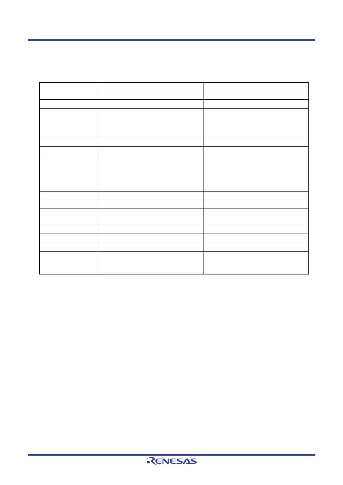
Table 18 - 10 shows the internal communication specification.
Note 1. For details, see CHAPTER 31 ELECTRICAL SPECIFICATIONS.
Note 2. For details, see CHAPTER 14 SERIAL ARRAY UNIT.
Table 18 - 10 Internal Communication Specification
Item
MCU RF Unit
CSI20 SPI
Target channel Serial array unit (SAU1) channel 0 (CSI20) Serial interface (SPI)
Internal pin to be used • SCK20, SI20, and SO20 inside-only pins
3-wire CSI communication pin
• P16 inside-only pin
Port pin for SEN control
• SCK, SIN, SOUT, and SEN inside-only pins
4-Wire SPI communication pin
Operating mode Transmission mode/Transmission/reception mode Transmission/reception mode
Master/slave Only master is supported. Slave
Interrupt Selectable from the following types.
• Transfer end interrupt
(in single-transfer mode)
• Buffer empty interrupt
(in continuous transfer mode)
None
Error detection flag Overrun/error detection flag None
Transfer data length Only 8 bits are supported. 8 bits
Transfer rate Within a range that satisfies the electrical
characteristics (AC specification)
Note 1
With in the range described in the left
Data phase
Only Type 1 is supported.
Note 2
Equivalent to the description in the left
Clock phase
Only Type 1 is supported.
Note 2
Equivalent to the description in the left
Data direction Only MSB is supported. MSB
Software setting As described above Not especially
(Controlling SEN pin to be fixed at the low level
allows the communication.)
 Loading...


