RL78/G1H CHAPTER 7 TIMER ARRAY UNIT
R01UH0575EJ0120 Rev. 1.20 Page 141 of 920
Dec 22, 2016
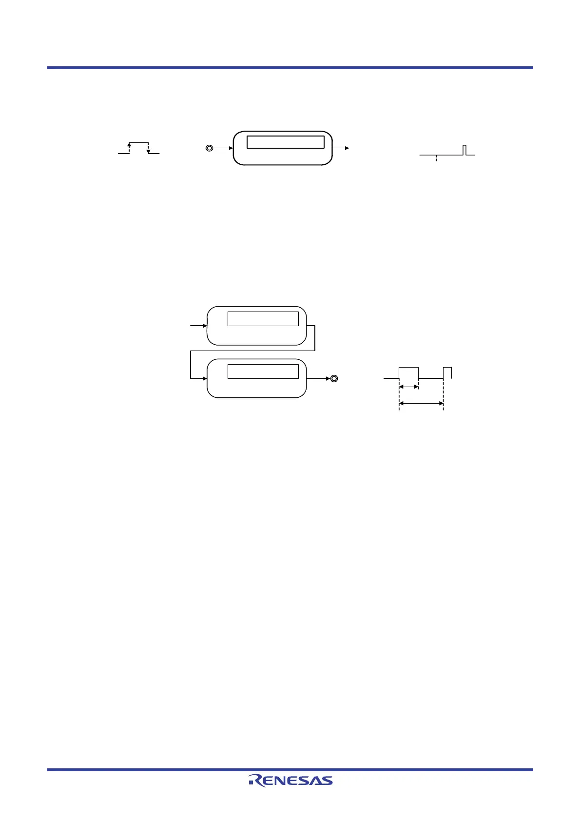
(6) Delay counter
Counting is started at the valid edge of the signal input to the timer input pin (TImn), and an interrupt is
generated after any delay period.
Remark 1. m: Unit number (m = 0, 1), n: Channel number (n = 0 to 3)
7.1.2 Simultaneous channel operation function
By using the combination of a master channel (a reference timer mainly controlling the cycle) and slave channels
(timers operating according to the master channel), channels can be used for the following purposes.
(1) PWM (Pulse Width Modulation) output
Two channels are used as a set to generate a pulse with a specified period and a specified duty factor.
Remark m: Unit number (m = 0, 1), n: Channel number (n = 0 to 3),
p, q: Slave channel number (n < p < q
≤ 3)
7.1.3 8-bit timer operation function (channels 1 and 3 only)
The 8-bit timer operation function makes it possible to use a 16-bit timer channel in a configuration consisting of
two 8-bit timer channels. This function can only be used for channels 1 and 3.
Caution There are several rules for using 8-bit timer operation function.
For details, see 7.4.2 Basic rules of 8-bit timer operation function (channels 1 and 3 only).
Interrupt signal
(INTTMmn)
Timer input
(TImn)
Compare operation
Channel n
Edge detection
Start
Operation clock
Compare operation
Channel n (master)
Compare operation
Channel p (slave)
Interrupt signal (INTTMmn)
Timer output
(TOmp)
Duty
Period
 Loading...


