RL78/G1H CHAPTER 7 TIMER ARRAY UNIT
R01UH0575EJ0120 Rev. 1.20 Page 142 of 920
Dec 22, 2016
7.2 Configuration of Timer Array Unit
Timer array unit includes the following hardware.
Note For details, see 5.5 Register Settings When Using Alternate Function.
Remark m: Unit number (m = 0, 1), n: Channel number (n = 0 to 3)
Figure 7 - 1 and Figure 7 - 2 show the timer array unit block diagram.
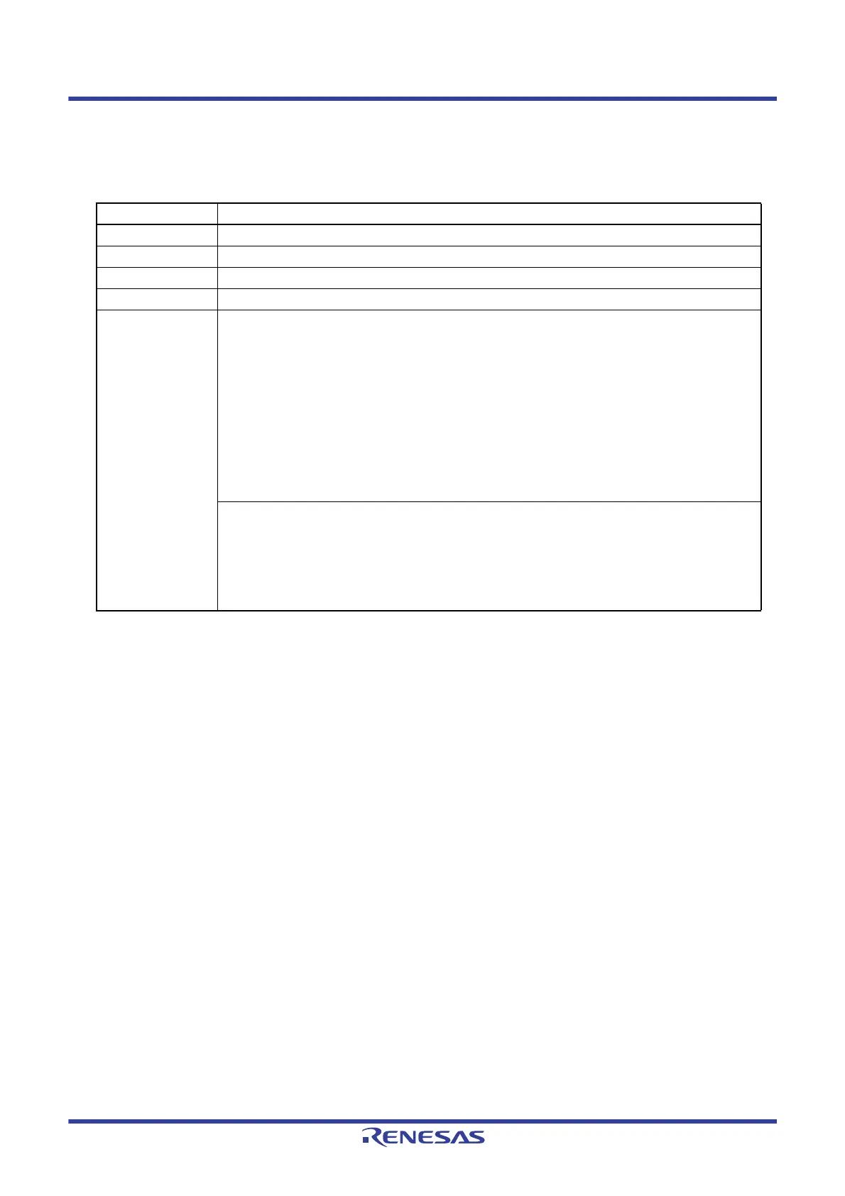
Table 7 - 1 Configuration of Timer Array Unit
Item Configuration
Timer/counter Timer count register mn (TCRmn)
Register Timer data register mn (TDRmn)
Timer input TI03
Timer output TO03
Control registers <Registers of unit setting block>
• Peripheral enable register 0 (PER0)
• Timer clock select register m (TPSm)
• Timer channel enable status register m (TEm)
• Timer channel start register m (TSm)
• Timer channel stop register m (TTm)
• Timer input select register 0 (TIS0)
• Timer output enable register m (TOEm)
• Timer output register m (TOm)
• Timer output level register m (TOLm)
• Timer output mode register m (TOMm)
<Registers of each channel>
• Timer mode register mn (TMRmn)
• Timer status register mn (TSRmn)
• Noise filter enable register 1 (NFEN1)
• Port mode register (PMxx)
Note
• Port register (Pxx)
Note
 Loading...


