RL78/G1H CHAPTER 2 CONNECTION BETWEEN MCU AND RF TRANSCEIVER
R01UH0575EJ0120 Rev. 1.20 Page 11 of 920
Dec 22, 2016
CHAPTER 2 CONNECTION BETWEEN MCU AND RF TRANSCEIVER
2.1 Connection Pins of MCU and RF Transceiver
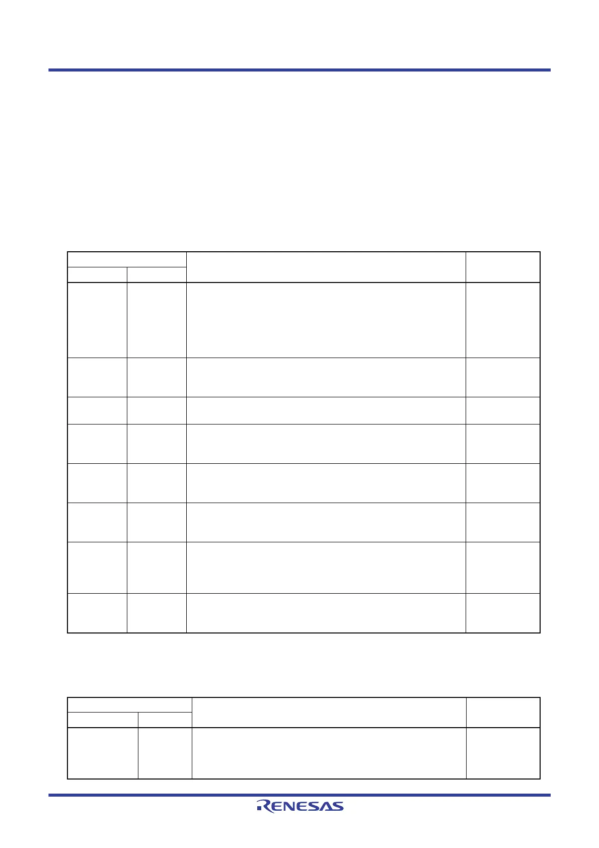
Table 2 - 1 lists the pins connected inside the RL78/G1H. Table 2 - 2 lists the pins which need to be connected on the
board by the user.
These pins require initial settings for an appropriate mode/level before starting communication with the RF
transceiver.
Note These pin outputs might be high impedance causing state of RF transceiver. These pins are required to fix by MCU in
this case. For details, see CHAPTER 18 RF TRANSCEIVER.
Table 2 - 1 Internal Pin Connection
Pin Name
Function Direction
MCU RF
unit
P10 OSCDRVSEL This is a switch signal that has the buffer drive capability for 48 MHz crystal
oscillator.
The buffer size (current) of the oscillator becomes smaller when
OSCDRVSEL is High.
The buffer size (current) of the oscillator becomes larger when OSCDRVSEL
is Low. P10, which is an internal I/O pin of MCU, controls OSCDRVSEL.
MCU to RF unit
P11 DON This is an enable signal of DCDC converter of RF unit. It becomes active
(DCDC converter is operable) when DON is set to High. P11, which is an
internal I/O pin of MCU, controls DON.
MCU to RF unit
P12 RFRESETB Hardware reset signal for the RF unit. RFRESETB=Low resets RF unit.
RFRESETB is controlled by P12 which is an internal I/O port of the MCU.
MCU to RF unit
P13/SO20 SIN Serial interface used for internal communication between blocks. Since it is
dedicated to internal communication (MCU: output data, RF unit: input data),
it cannot be used for communication with external modules.
MCU to RF unit
P14/SI20
SOUT
Note
Serial interface used for internal communication between blocks. Since it is
dedicated to internal communication (MCU: input data, RF unit: output data),
it cannot be used for communication with external modules.
RF unit to MCU
P15/SCK20 SCLK This is an operation clock of Serial interface for internal communication
between blocks. Since it is dedicated to internal communication, it cannot be
used for communication with external modules.
MCU to RF unit
P16 SEN This is a communication enable control signal of Serial interface (RF unit) for
internal communication between blocks.
It becomes active (Serial communication enabled) when SEN is Low. P16,
which is an internal I/O of MCU, controls SEN.
MCU to RF unit
P30/INTP3
INTOUT
Note
Interrupt request signal from RF transceiver. If an interrupt source is
generated in RF unit, the status is output from INTOUT. MCU receives this
status at INTP3, and can execute the interrupt processing.
RF unit to MCU
Table 2 - 2 Pins Externally Connected on User Board
Pin Name
Function Direction
MCU RF unit
P130 STANDBY This is a power-down control signal of RF unit. RF unit becomes operable
when STANDBY is High. RF unit enters the SLEEP state when STANDBY
is Low. P130, which is an I/O pin of MCU, controls STANDBY. Connect
P130 and STANDBY externally (on the board).
MCU to RF unit
 Loading...


