RL78/G1H CHAPTER 17 EVENT LINK CONTROLLER (ELC)
R01UH0575EJ0120 Rev. 1.20 Page 543 of 920
Dec 22, 2016
17.4 ELC Operation
The path for using an event signal generated by a peripheral function as an interrupt request to the interrupt control
circuit is independent from the path for using it as an ELC event. Therefore, each event signal can be used as an
event signal for operation of an event-receiving peripheral function, regardless of interrupt control.
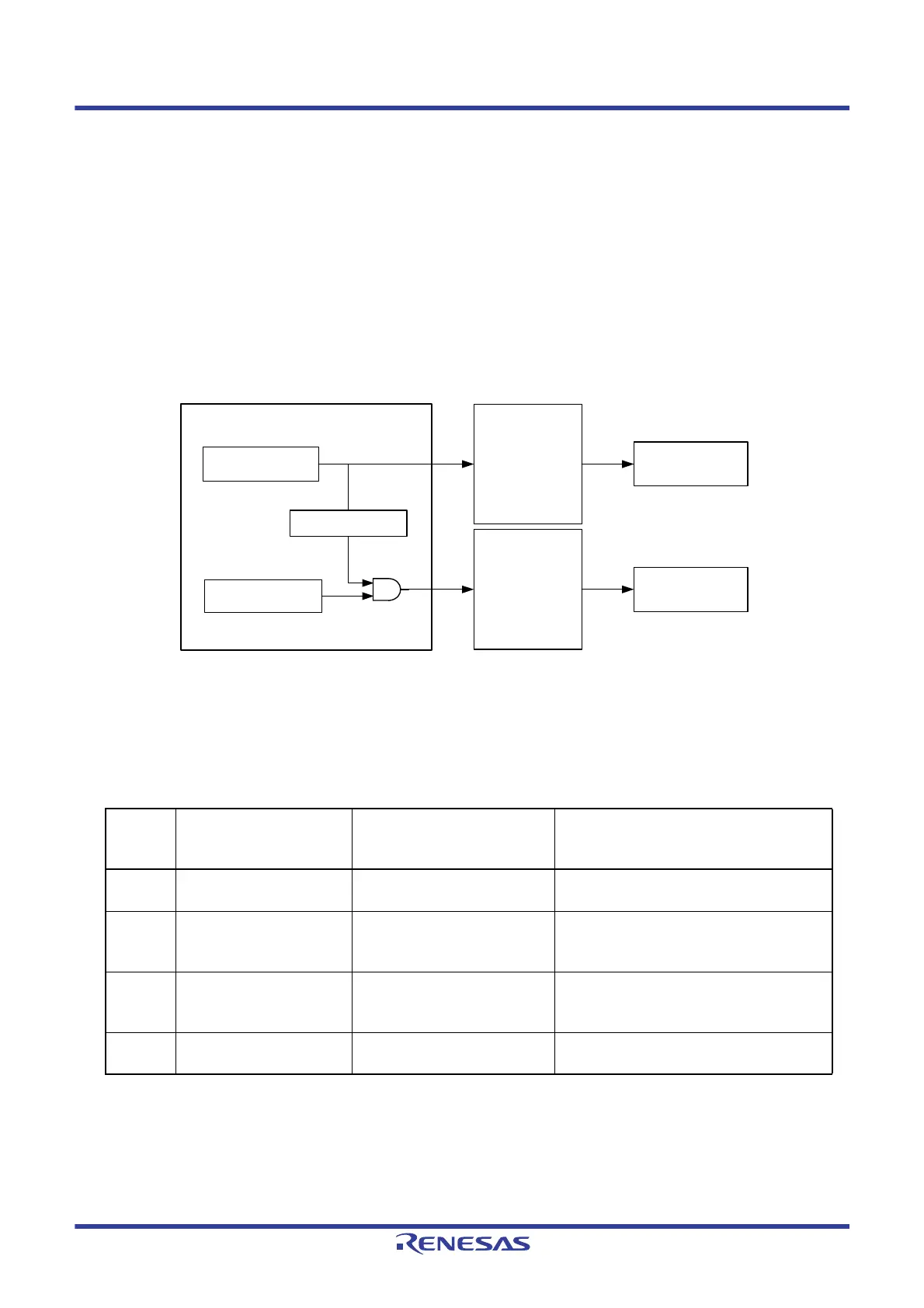
Figure 17 - 3 shows the Relationship Between Interrupt Handling and ELC. The figure show an example of an
interrupt request status flag and a peripheral function possessing the enable bits that control enabling/disabling of
such interrupts.
A peripheral function which receives an event from the ELC will perform the operation corresponding to the event-
receiving peripheral function after reception of an event.
Figure 17 - 3 Relationship Between Interrupt Handling and ELC
Note Not available depending on the peripheral function.
Table 17 - 2 lists the response of peripheral functions that receive events.
Table 17 - 2 Response of Peripheral Functions That Receive Events
Event
Receiver
No.
Event Link Destination
Function
Operation after Event Reception Response
1 A/D converter A/D conversion An event from the ELC is directly used as a
hardware trigger of A/D conversion.
2 Timer array unit 0
Timer input of channel 0
Delay counter
Input pulse width measurement
External event counter
The edge is detected 3 or 4 cycles of f
CLK after
an ELC event is generated.
3 Timer array unit 0
Timer input of channel 1
Delay counter
Input pulse width measurement
External event counter
The edge is detected 3 or 4 cycles of f
CLK after
an ELC event is generated.
4 Timer RJ Count source An event from the ELC is directly used as the
count source of timer RJ.
Peripheral function (Event output side)
Peripheral function
(Event receive side)
ELC
Interrupt request
(Event signal)
Interrupt enable
control
Note
Interrupt control
circuit
CPU
Status flag
Note
 Loading...


