RL78/G1H CHAPTER 15 SERIAL INTERFACE IICA
R01UH0575EJ0120 Rev. 1.20 Page 430 of 920
Dec 22, 2016
15.2 Configuration of Serial Interface IICA
Serial interface IICA includes the following hardware.
Remark n = 0, 1
(1) IICA shift register n (IICAn)
The IICAn register is used to convert 8-bit serial data to 8-bit parallel data and vice versa in synchronization with
the serial clock. The IICAn register can be used for both transmission and reception.
The actual transmit and receive operations can be controlled by writing and reading operations to the IICAn
register.
Cancel the wait state and start data transfer by writing data to the IICAn register during the wait period.
The IICAn register can be set by an 8-bit memory manipulation instruction.
Reset signal generation clears IICAn to 00H.
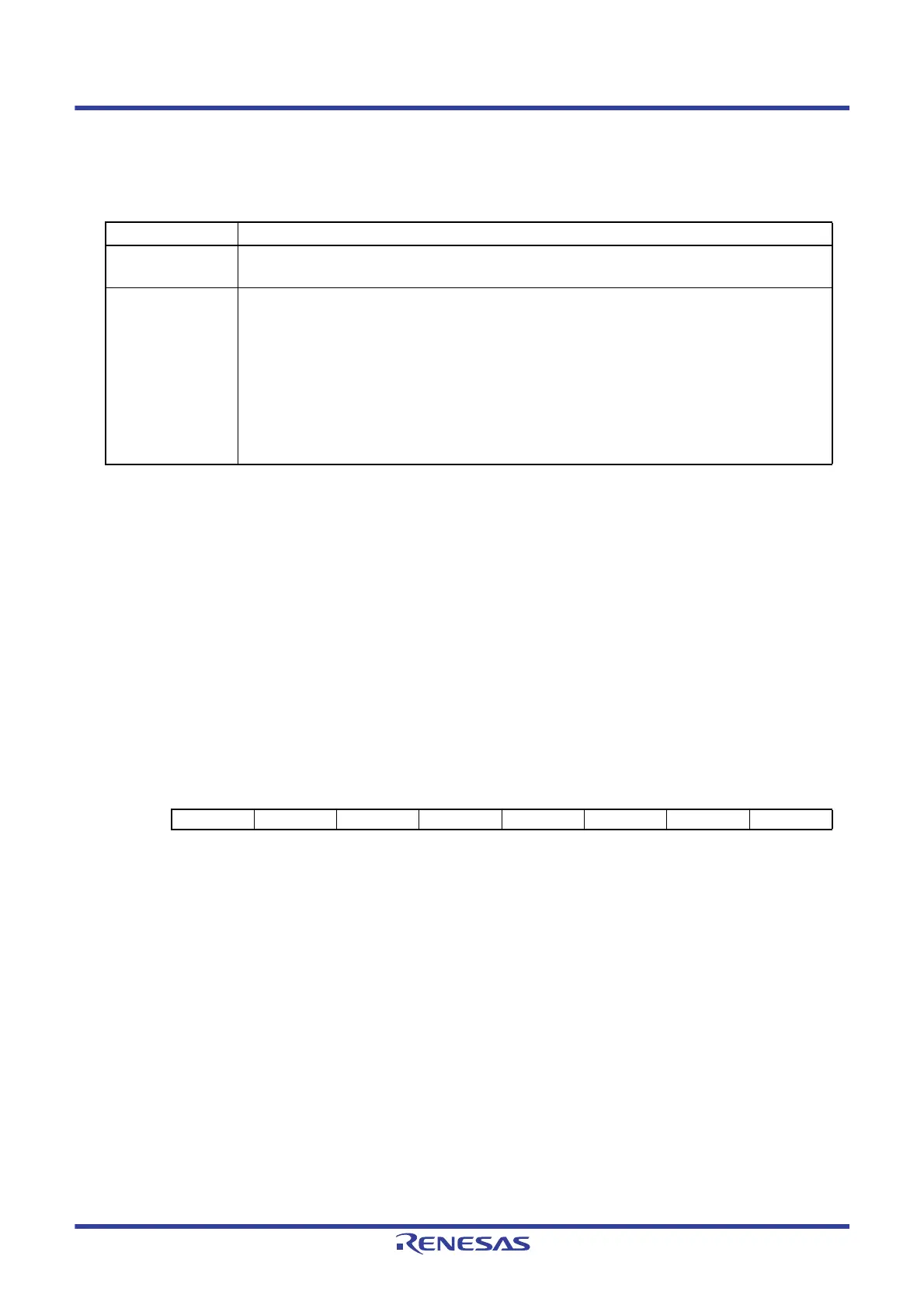
Figure 15 - 3 Format of IICA shift register n (IICAn)
Caution 1. Do not write data to the IICAn register during data transfer.
Caution 2. Write or read the IICAn register only during the wait period. Accessing the IICAn register in a
communication state other than during the wait period is prohibited. When the device serves as the
master, however, the IICAn register can be written only once after the communication trigger bit
(STTn) is set to 1.
Caution 3. When communication is reserved, write data to the IICAn register after the interrupt triggered by a
stop condition is detected.
Remark
n = 0, 1
Table 15 - 1 Configuration of Serial Interface IICA
Item Configuration
Registers IICA shift register n (IICAn)
Slave address register n (SVAn)
Control registers
Peripheral enable register 0 (PER0
)
IICA control register n0 (IICCTLn0)
IICA status register n (IICSn)
IICA flag register n (IICFn)
IICA control register n1 (IICCTLn1)
IICA low-level width setting register n (IICWLn)
IICA high-level width setting register n (IICWHn)
Port mode register 6 (PM6
)
Port register 6 (P6)
Address: FFF50H (IICA0), FFF54H (IICA1) After reset: 00H R/W
Symbol76543210
IICAn
 Loading...


