REPLACEMENT AND ADJUSTMENT
SM 23 B513/B531
Output
Jogger Unit/
Punch Unit
B513/B53131
3.8 PUNCH UNIT B531 (OPTION)
3.8.1 PUNCH POSITION ADJUSTMENT
The position of the punched holes can be adjusted in two ways.
Front to Rear Adjustment
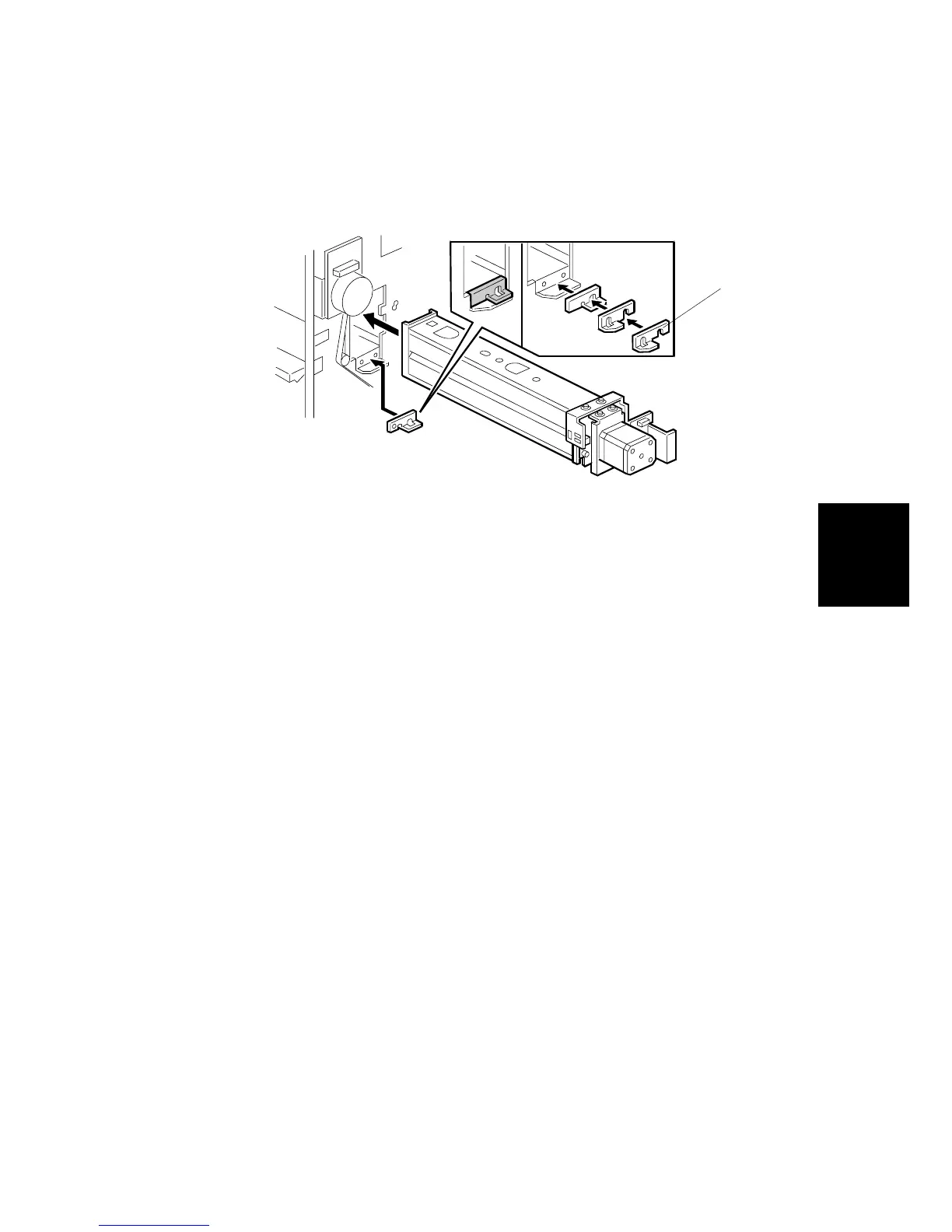
Three spacers [A] are provided with the punch unit for manual adjustment of the
hole position in the main scan direction:
• 2 mm (x 1)
• 1 mm (x 2)
NOTE: One spacer was installed at installation and the remaining spacers were
fastened with a screw to the rear frame of the finisher under the rear cover
and slightly above the lock bar.
Right to Left Adjustment
The position of the punched holes can be adjusted right to left in the sub scan
direction with SP6-113 Punch Hole Position Adjustment. The position can be
adjusted in the range ±7.5 mm in 0.5 mm steps. The default setting is 0.
Press the key to toggle the ± selection. A +VE value shifts the punch holes left
toward the edge of the paper, and a -VE value shifts the holes right away from the
edge.
B531R101.WMF
[A]
 Loading...