1、FRAME COMPONENT 9
CHK
AD
J
NO. PART NO.
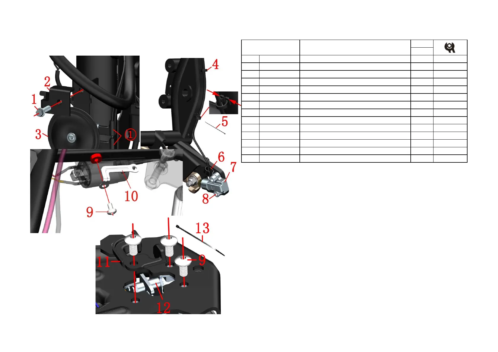
1 1251100-061093 M6×22Hex flange face full thread bolt 1
-
R Front disc brake tubing bracket No. 2 1
3 1184200-004000 ZT310 Horn 1
-
5 1224100-037000 0 grade flame retardant cable tie (black 3.6×295) 2
6 1274100-095000 Side bracket flameout switch wire fixing bracket 1
7 1184100-012000 Side bracket flameout switch wire fixing bracket 1
8 1250205-040095 GB70.1Hexagon socket bolt M8×16 2
9 1251100-101000 Non-standard bolt M6×12 (304 stainless steel) 4
10 1274200-291000 ZT310-R ignition coil connecting bracket 1
11 1224200-205000 ZT310 electronic cushion lock guide block 1
12 1274100-058000 ZT310 electronic cushion lock 1
13 1224100-037000 0 grade flame retardant cable tie (black 3.6×295) 2
Electrical device component-2
PROCEDURE:
●Horn
Pull off the horn plug①, One hang hold the horn(3) and the other remove the bolts(1) with tool, and move away
the bracket(2)and remove the horn.
●Flameout switch
Find and unplug the flameout switch plug;The wire buckle (4) is pressed inward in the direction of the arrow
shown and then pulled out forcefully, cut off the cable tie(5).Use the inner hexagon tool to loosen the bolt and
remove the bracket(6) and flameout switch(7).
●Ignition coil connecting bracket
Remove the bolt ⑼ with a 4# hex wrench, then the ignition coil connecting bracket ⑽ can be taken off.
●Cushion lock
Find and pull off the cable connector of the cushion lock, cut off the cable tie⒀, loosen the bolts⑼ and remove
the cushion lock guide block⑾ and cushion lock⑿.
CAUTION:
●Can't pull the cable directly when pull off the plug① and ②.
●Pay attention to the strength and direction of force when removing the buckle.
●Be careful not to overcharge the charging time. See the instructions for battery use and maintenance.
●From October 22, 2020,one guide block⑾ have been added to the electronic cushion lock.
FIG.2 FRAME&ELECTRONIC
PARTS COMPONENT
 Loading...