7、FRONT FORK COMPONENT 62
CAUTION:
●When the front wheel hollow shaft is removed, the bolts on the right front shock absorber bottom tube
are loosened slightly. If the hollow shaft is too tight, the loose shaft sleeve cannot be fixed.
●Care should be taken when disassembling the tires and rims to prevent damage to the parts.
●After replacing the tire, check for leaks and balance.
●Unqualified tire repair fluid may corrode the rim and cause safety hazards.
●Insufficient tire pressure may cause steering jitter, abnormal wear, etc.; there is a risk of puncture in
summer tire pressure.
●Maintenance project
Tires: The tires should be regularly inspected for cracks, cracks, air pressure, etc. If the tread wear
indicator has been worn out, the tire of the same specification type must be replaced. Refer to the relevant
content of the manual for details. The tires are semi-hot melt rubber products and are not suitable for use
in areas with low temperatures. When the outdoor temperature is too low, it is recommended to store the
vehicle in a place with a high temperature or indoors to prevent freezing cracks.
Normal temperature: standard 250 kPa.
Rim: Check the rim for any deformation, cracks, etc. Rotate the rim horizontally to check for sticking,
swinging, etc.Rim seal φ42 × φ28 × 7; bearing model: 6004-2RS.
Axle: Use a dial indicator to check for deformation and bending.
Brake disc: After the new brake disc is replaced, it should be carried out for about 300 km to fully fit in
order to achieve the best braking effect. Care should be taken to ensure adequate braking distance during
running-in.
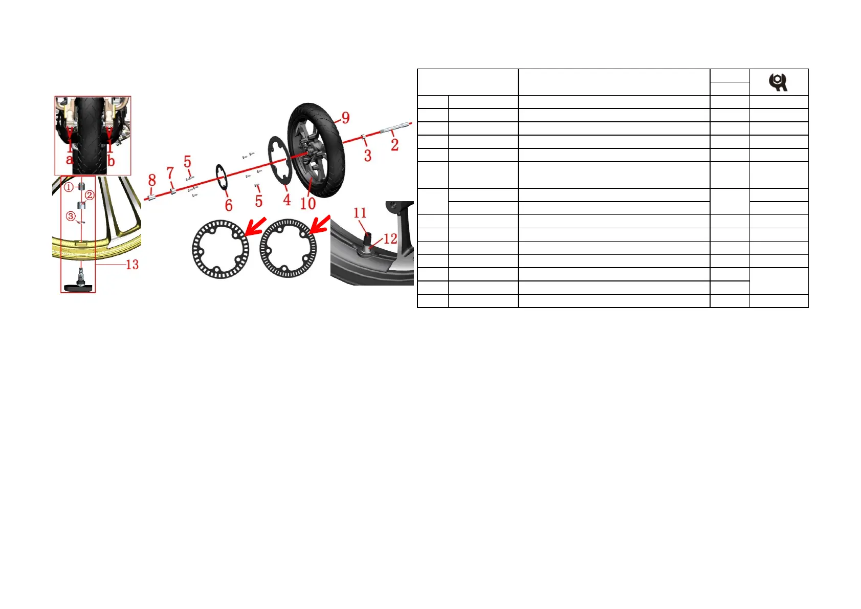
PROCEDURE:
●Tire and wheel component
Remove the 2 bolts (1) on the left front shock absorber bottom "b" with the Allen tool. Hold the front wheel first
and then remove the hollow shaft (2) with the internal hexagon tool, remove the left sleeve (3), and move the
front wheel component downward to remove the right sleeve (7) and front wheel component. Finally, use the
hexagonal tool to remove the 2 bolts (1) of the right front shock absorber "a", remove the right fixing sleeve (8) .
●Brake disc, ABS ring gear
Remove the bolt (5) with a hexagon and then remove the ABS ring gear (6). Remove the bolt (5) with the
hexagon socket tool and remove the brake disc (4).Some vehicles produced in late May 2019 and produced
before that were 40 teeth, produced after that are 60 teeth; the two kinds of ring gears could not be mixed.
●EURO IV:Tire and rim component
Unscrew the valve cap ⑾ and use the tool to release the air. Remove the tire (9) with a professional tire
extractor. Finally remove the tire valve⑿ with a suitable tool then take off.
●EURO V:Tire pressure wireless built-in sensor
Remove the valve cap① that comes with the tire pressure wireless built-in sensor,use a tool to release the air,
and then use a professional tire puller to remove the front tire ⑼, taking care to avoid the tire pressure sensor.
Finally, use a 12# wrench to remove the valve nut ② and the flat washer ③, and then remove the tire pressure
sensor.
CHK
ADJ
NO. PART NO. PART NAME QTY CAUTION
1 1250205-023000 GB70.1 Hexagonal M8×35 (color zinc) 4 20N.m
2 1094100-033000 ZT250-R front wheel hollow shaft 1
3 1094100-008000 ZT250-R front wheel left sleeve 1
4 1100100-418000 ZT310-R1 front brake disc (300×5.0) 1
1274200-058000 ABS induction ring gear (60 teeth)
1274200-168021 ABS induction ring gear (40 teeth)
7 1094100-036000 ZT250-R front wheel right sleeve 1
8 1094100-037000 ZT250-R front wheel right fixed bushing 1
9 1230100-486000 ZT310-T 110/70R17 (CM509) tire 1
10 1094200-026000
ZT310-R black front wheel(3.0×17)
1
11 1230200-006000
HJ100-D tire valve cap
1
12 1230100-047000
HJ125-3A environmental tubeless tire valve
1
13 1184200-155000 ZT310 tire pressure wireless built-in sensor 1 EURO V
Front wheel component
6 1
EURO IV
Non-standard hexagon socket bolt M8×25
(environmental color)
10 25N.m
Fig. 17 FRONT FORK
COMPONENT
5 1251100-117093

 Loading...