1、FRAME COMPONENT 11
CHK
ADJ
NO. PART NO.
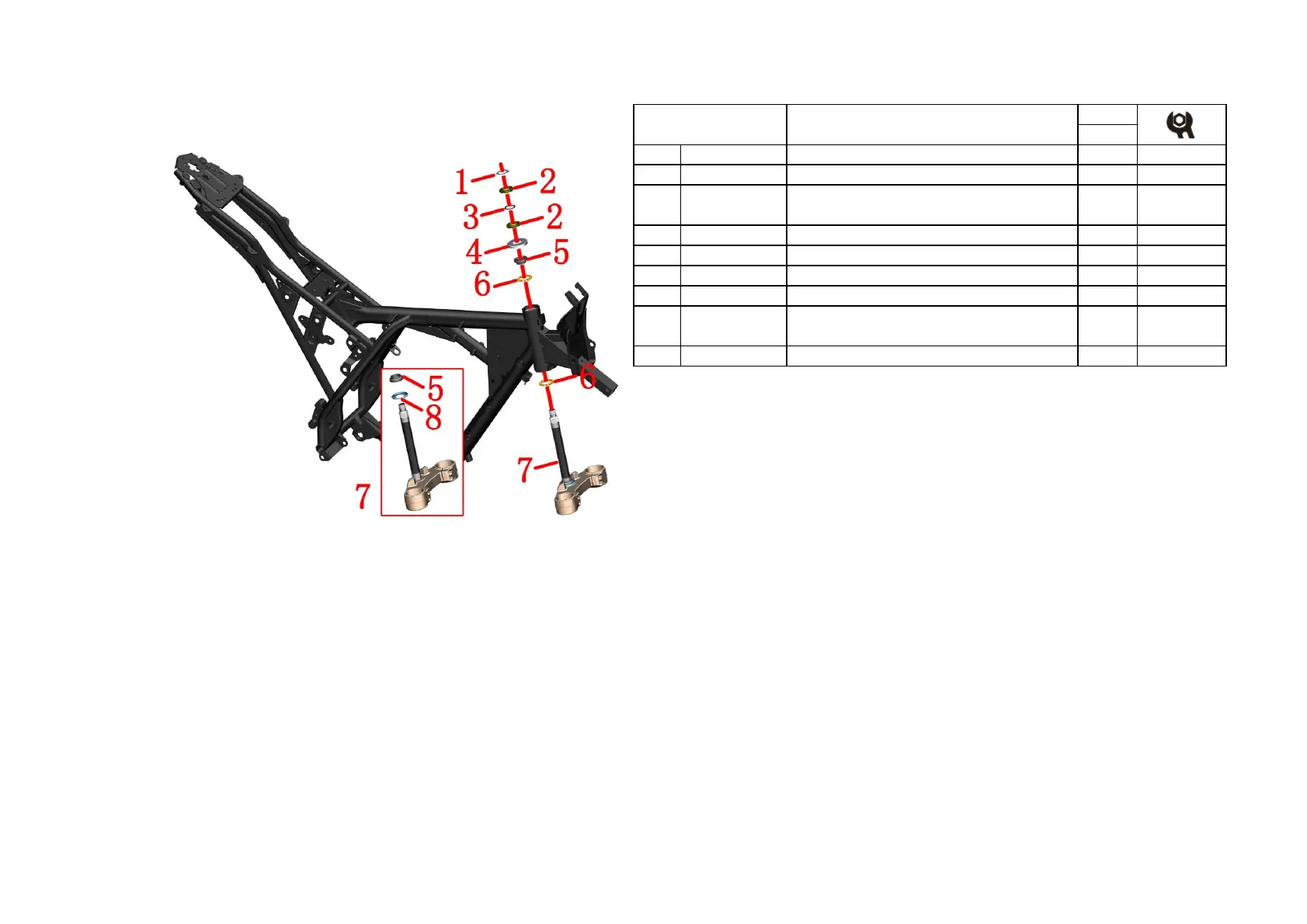
1 1134100-007000 ZT250-S Adjust nut lock washer 1
3 1244100-015000 ZT250-S Adjusting nut pad 1
4
-
S Dust cover to the column 1
5
-
6
-
8
-
S Directional column dust cover
1
PROCEDURE:
●Remove the cylinder
Remove the lock washer(1)Use the special four-jaw sleeve or hook wrench to remove the upper
adjustment nut (2).
Remove the rubber pad(3).
Hold the lower connection board assembly(7) in one hand,and loosen the adjustable nuts(2) with the
special four-jaw sleeve or hook wrench in the other hand.
Remove the upper dust cover(4) .
Remove the lower connection board assembly(7) .
Remove the shaft ring (5) and the connecting steel ball (6) on the upper part of the front riser.
Remove the lower connection board assembly(7).
Remove the connecting steel ball on the lower connection board assembly(7).
●Installation:
When reassembling, the joint steel balls should be evenly coated with grease, pay attention to the amount
of grease.
The adjusting nut close to the upper dust cover (4) requires a torque of about 14 N.m, so that it can be
flexibly rotated without jamming.
The upper adjustment nut only needs to be screwed to the bottom nut groove, and should not be too tight
to prevent the rubber pad (3) from being deformed too much.
CAUTION:
●It needs to remove the head assembly,handlebar assembly and front shock absorber at first.
●
Pay attention to fixing the vehicle to be repaired during the disassembly process to prevent accidents caused by
dumping.
●
Check whetreher there are some abnormal phenomena such as partial grinding and rust on the connecting steel
ball. If there are, please go to Shengshi official website to buy regular accessories. If not, be sure to clean the old
grease and then smear.Must check the joint ball for missing when reassembling.
●It is reasonable to adjust the steering tightness. If it is too loose, it will cause slight shaking and abnormal noise
when the front of the vehicle is in emergency braking. If it is too tight, the rotation will be inflexible, resulting in
safety hazards.
●
If you have the ability and have the right tools, you can replace the shaft collar (5) and the lower dust cover (8)
at the lower joint assembly. Pay attention to the protection of the lower plate during the replacement process;
after replacement, be sure to check the parallelism between the column and the shock absorbing hole, and the
verticality of the column and the lower plate.
●When the front fork has a slight sway or the steering wheel swings while braking.
First check whether the front tire pressure is the recommended air pressure at normal temperature: normal
temperature: standard 250kPa.
● If it is lower than the recommended air pressure, first inflate the front tire air pressure to 350kPa, and then
deflate to the test drive to check whether it is released. If the front wheel is otherwise lifted and turned to check
the tread, if it is eccentric or deformed, the front tire needs to be replaced. If you need to re-adjust the adjustment
nut.
FIG.4 FRAME&ELECTRONIC
PARTS COMPONENT
Steering rack component
1134100-015000
ZT250-S Lower joint plate (homemade / with bead
top) component
1
2 1251300-046093
ZT250-S Directional column adjustment nut M24X1
2
7

 Loading...