7、FRONT FORK COMPONENT 66
CHK
ADJ
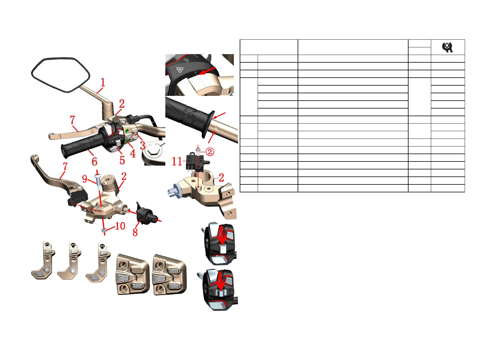
NO. PART NO. PART NAME QTY CAUTION
1 1194100-001000 ZT250-S left rear view mirror 1
2 1134200-011000 ZT310-V left hand rocker arm component 1
1184200-085000 ZT310-X left hand switch(TFT) Stop selling
1184200-144000 Second Generation Left Handlebar Switch TFT) New
1184100-106000 ZT310-X left hand switch Stop selling
1184200-131000 ZT310-X left hand switch(without ABS button) Stop selling
1184200-150000
Second Generation Left Handlebar Switch (Liquid crystal)
New
4 1250205-031091 GB70.1M6×30 (stainless steel) 2
1184200-066000
-
X left hand switch (clutch line length 100)
Stop selling
1184200-141000
-
X1 left handlebar switch
New
6 1244100-041000 ZT250-R left hand rubber sleeve 1
7 1134100-029000 ZT250-R balance block subcontracting component 1
8 1134200-010000 ZT310-V left hand rocker arm (machine plus) 1
9 1244200-046000 ZT310-V protective rubber sleeve 1
10 1251100-198000 Non-standard bolt M6×13-φ8×20 1
11 1251300-073000 GB/T6185 nut M6 1
12 1184100-107000 ZT250-R clutch switch 1
Fig.23 FRONT FORK
COMPONENT
Left hand component
New
Old
3
PROCEDURE:
● left rear view mirror, left switch, rocker arm
Remove the clutch line by referring to the “Replace Clutch Line” procedure. Remove the left rear view mirror
⑴, rocker base⑵, left sub switch⑶, bolt⑷, left switch⑸, and rocker arm⑻ by referring to the steps in "Right
Handle Assembly" and "Add Brake Fluid, Adjusting Rocker Arm".
●Left hand rubber sleeve
Can be soaked in hot water for about 10 minutes before use a blow gun to blow the left hand grip between the
rubber sleeve⑹ and the direction handle tube while moving the rubber sleeve outward.
●Replace the left hand rocker arm and clutch switch
Fix the bolt⑽ with a hexagonal tool, then remove the nut⑾ with a sleeve or a wrench, remove the bolt⑽ and
then remove the left hand rocker arm⑻. First unplug the clutch switch, then remove the bolt① with a Phillips
screwdriver and remove the clutch switch⑿. The rotation adjustment nut can adjust the distance between the
rocker arm and the left hand rubber sleeve to adapt to the feel of different drivers.
CAUTION:
●When assembling the switch, first align the locating hole under the switch with the direction to align the
Threaded Hole on the tube, then assemble the Phillips head bolt first, and then install the hexagon socket head
bolt. Be sure to pay attention to the cable that cannot be pressed inside the switch; the torque should not be too
large.The old model will be discontinued; the old switch can be replaced directly with the new one.
1
5 1
TFT
TFT

 Loading...