Rockwell Automation Publication MOTION-UM003K-EN-P - January 2019 149
Axis Scheduling Chapter 7
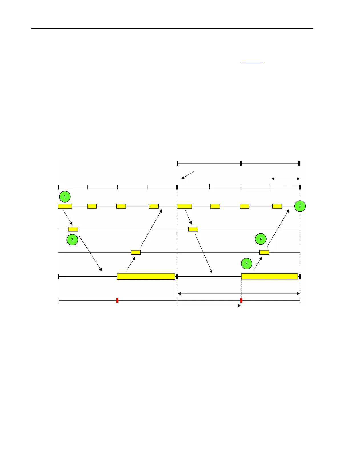
Two Cycle Timing
The Two Cycle Timing Model that is shown in Figure 23 begins with the
device transmitting the D-to-C connection packet to the controller at the
beginning of the update cycle. In this case, the Controller Task does not start
until half way through the update cycle. This start point allows more time for
the D-to-C connection packet to reach the controller before the Motion
Planner task runs. Unlike the One Cycle Timing Model, the C-to-D
connection packet is not transmitted back to the device until the next time the
Motion Planner task runs. This delay again allows more time for the C-to-D
connection packet to reach the device. It takes two connection cycles to
complete the I/O data transaction with the device.
Figure 23 - Integrated Motion on the EtherNet/IP Network Two Cycle Timing Model
Device Interrupt Timer
Device Interrupt Service
Motion D-to-C I/O Connection
Motion C-to-D I/O Connection
Controller Task
Controller Task Timer Events
Input Traffic
Output Traffic
Connection Update
Device Update Period
Actual Position
Command Position
Controller Update Period (1 ms)
250 μs
Controller Task
Phase Offset
~500 μs
Motion Planner
Motion Planner

 Loading...


