248 Rockwell Automation Publication MOTION-UM003K-EN-P - January 2019
Chapter 11 Commission an Axis
• Any additional unsuppressed resonances are present.
Status Bits
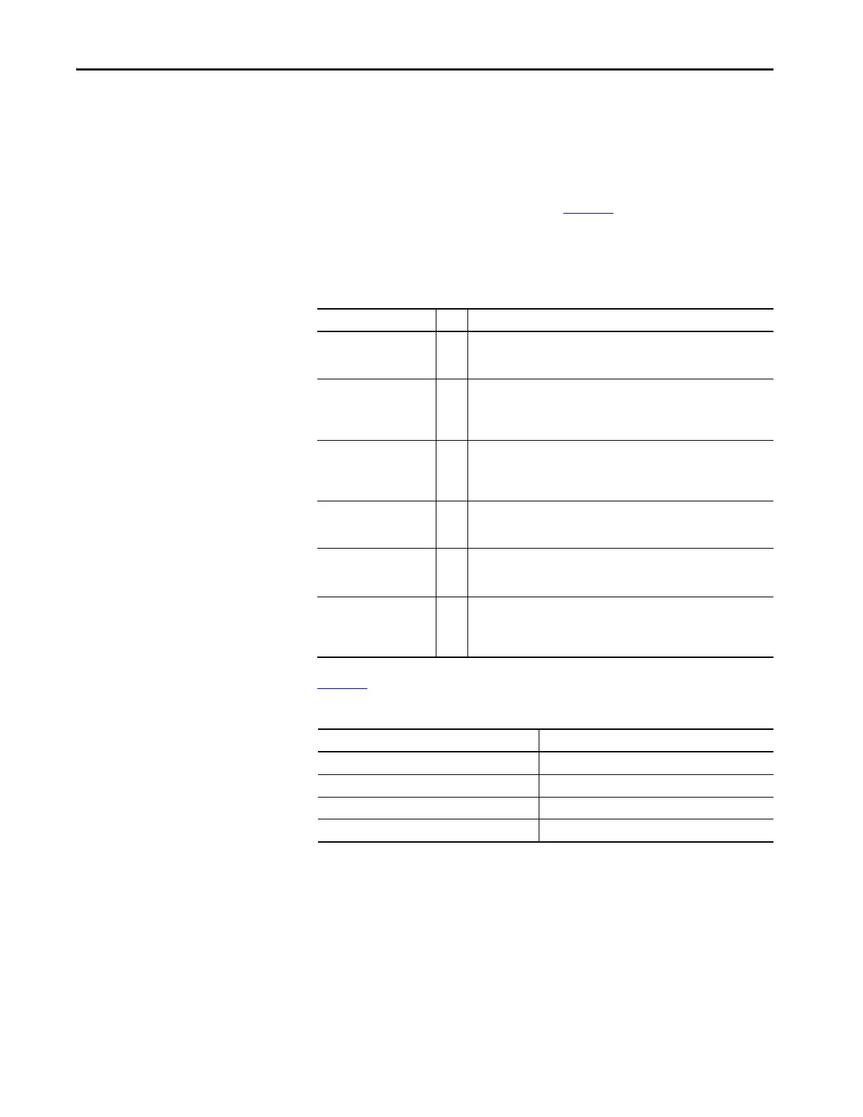
The Adaptive Tuning status bits shown in Tab le 52 let you create custom
Ladder Logic to trap errors, debug, and react to changes. This function is
useful for condition monitoring, diagnostics, and preventative maintenance
purposes.
Table 53
describes when output parameters are reset to the default values.
Table 52 - Adaptive Tuning Status Bits
Name Bit Description
Torque Notch Filter
Frequency Detected Status
0 Set when resonances are identified between the low and high frequency
limits with magnitudes above the tuning threshold. Normally, this bit is
clear. This bit is also cleared when the axis transitions to the Running state.
Torque Notch Filter Tune
Unsuccessful Status
1 Set when the tracking notch filters do not eliminate all identified
resonances. Normally, this bit is clear. This bit is also cleared when the axis
transitions to the Running state or when Adaptive Tuning transitions from
Disable mode to one of the Tracking Notch modes while in the running state.
Torque Notch Filter Multiple
Frequencies Status
2 Set when multiple resonances are identified between the low and high
frequency limits with magnitudes above the tuning threshold. Normally, this
bit is clear. This bit is also cleared when the axis transitions to the Running
state.
Torque Notch Filter
Frequency Below Limit
Status
3 Set when resonances are identified below the low frequency limit with
magnitudes above the tuning threshold. Normally, this bit is clear. This bit is
also cleared when the axis transitions to the Running state.
Torque Notch Filter
Frequency Above Limit
Status
4 Set when resonances are identified above the high frequency limit with
magnitudes above the tuning threshold. Normally, this bit is clear. This bit is
also cleared when the axis transitions to the Running state.
Adaptive Tune Gain
Stabilization Status
5 Set when the gain scaling factor is not equal to one. This setting indicates
that the Adaptive Tuning is controlling the low pass filter and adjusting servo
loop gains to stabilize the system. Normally, this bit is clear. This bit is also
cleared when the axis transitions to the Running state.
Table 53 - Adaptive Tuning Reset Behavior
Parameter When Reset to Default Value
Torque Notch Filter Frequency Estimate Disabled, Gain Stabilization
Torque Notch Filter Magnitude Estimate When a resonance is not identified
Torque Low Pass Filter Bandwidth Estimate Disabled, Tracking Notch Filter
Adaptive Tuning Gain Scaling Factor Disabled, Tracking Notch Filter

 Loading...


