Rockwell Automation Publication MOTION-UM003K-EN-P - January 2019 191
Axis Configuration Examples for the PowerFlex 755 Drive Chapter 9
Example 2: Position Loop
with Dual Motor Feedback
Via a UFB Feedback Device
This example describes how to create an AXIS_CIP_DRIVE axis that is
associated to a PowerFlex 755 drive with dual motor feedback via a universal
feedback device, catalog number 20-750-UFB-1.
See Create an Axis for a PowerFlex 755 Drive on page 109
for more
information about feedback devices.
1. Once you have created an AXIS_CIP_DRIVE, open the Axis
Properties.
2. From the Axis Configuration pull-down menu, choose Position Loop.
3. From the Feedback Configuration pull-down menu, choose Dual
Feedback.
When you choose the configuration type, it determines the Control
Mode.
See the Integrated Motion on the EtherNet/IP Network Reference
Manual, publication MOTION-RM003
.
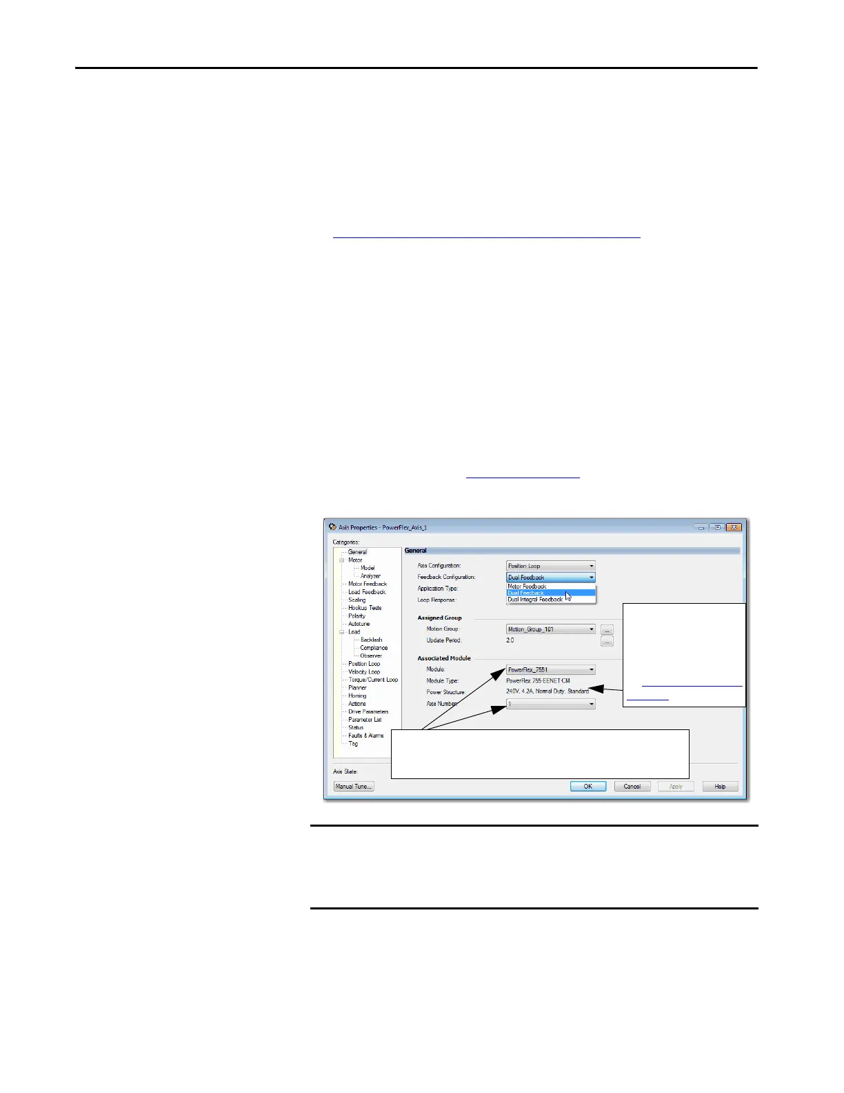
Figure 59 - Example 2: Position Loop with Dual Feedback, General Dialog Box
Now that you defined the axis as being a Position Loop with Dual
Feedback axis, the Motor Feedback, and Load Feedback dialog boxes
become available.
TIP Remember that you already assigned the feedback device when you
added the drive to your project.
IMPORTANT After you have configured the axis and you change the Axis Configuration
type or the Axis Number, some of the configuration information is set to
default values. This change can cause some previously entered data to be
reset back to its default setting.
Displays the type of drive you
selected and power structure
you assigned to via the
PowerFlex 755 drive Module
Properties.
See Add a PowerFlex 755 Drive
on page 99.
The newly created PowerFlex 755 drive module name is the default. The Axis
Number defaults to 1, indicating the primary axis of the drive. Axis Number 2
is used only for configuring a Feedback Only axis.

 Loading...


