24 Rockwell Automation Publication MOTION-UM003K-EN-P - January 2019
Chapter 2 Create a Project for Integrated Motion on the EtherNet/IP Network
Set Time Synchronization
This technology supports highly distributed applications that require time
stamps, sequence of events records, distributed motion control, and increased
control coordination. All controllers and communication modules must have
time synchronization that is enabled for applications that use integrated
motion on the EtherNet/IP™ network.
Time synchronization in the Logix system is called CIP Sync. CIP Sync
provides a mechanism to synchronize clocks between controllers, I/O, and
other devices that are connected over CIP™ networks and the ControlLogix® or
CompactLogix™ backplane. The device with the best clock becomes the
Grandmaster time source for your system.
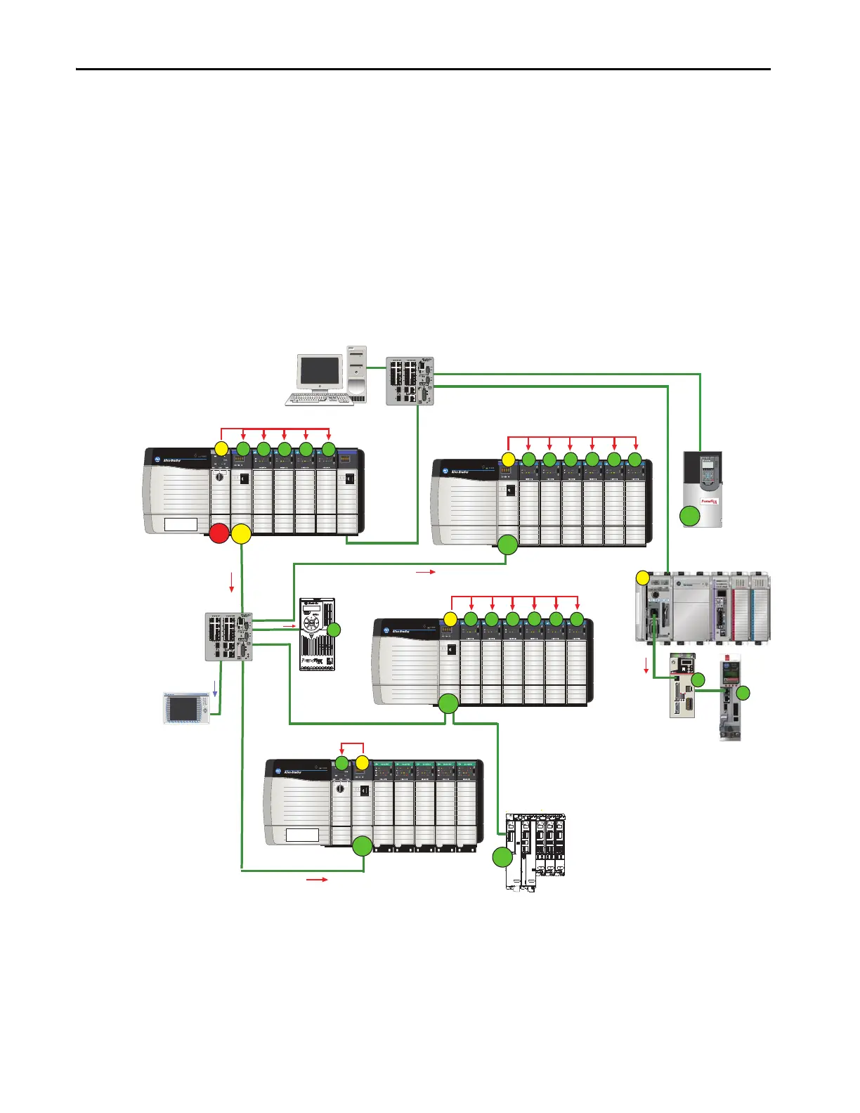
Figure 1 - Star Topology with the ControlLogix Controller as the Grandmaster
EtherNet/IP™
Logix5563
EtherNet/IP™
EtherNet/IP™
SOE INTPUTSOE INTPUT SOE INTPUT SOE INTPUT SOE INTPUT SOE INTPUT
EtherNet/IP™
SOE INTPUTSOE INTPUT SOE INTPUT SOE INTPUT SOE INTPUT SOE INTPUT
Logix5563
EtherNet/IP™
SOE INTPUT SOE INTPUT SOE INTPUT SOE INTPUT
S
P2=1
P2=2
GM
CIP Sync
CIP Sync
CIP Sync
L
7
X
S
O
E
S
O
E
S
O
E
S
O
E
E
N
2
T
S
O
E
S
O
E
S
O
E
S
O
E
S
O
E
S
O
E
E
N
2
T
E
N
2
T
S
O
E
S
O
E
S
O
E
S
O
E
S
O
E
S
O
E
E
N
2
T
E
N
2
T
D
I
O
D
I
O
D
I
O
D
I
O
D
I
O
L
7
X
CIP Sync
S
M
S
S S S
CIP Sync
S
M
S
S
S
S
S
CIP Sync
S
M
S
S
S
S
S
CIP Sync
M
S
CIP Sync
Com
IN2
IN1
Ref
M
NTP
MOD
NET
MOD
NET
MOD
NET
MOD
NET
2
1
1
1
4
I/O
I/O
6
5
10
2
1
2
1
2
1
1
I/O-A
6
510
1
I/O-B
6
510
1
I/O-A
61
I/O-B
6
510510
UFB
UFB-A UFB-B
UFB-A UFB-B
D+
D-
D+
D-
D+
D-
MF-A MF-B MF-A MF-B
D+
D-
MBRK
+
-
MOD
NET
2
1
1
I/O-A
61
I/O-B
6
510510
UFB-A UFB-B
D+
D-
MF-A MF-B
D+
D-
5700
5700
5700
5700
5700
S
S
S
S
M
350
MEM
A=ENABLE
B= REGEN
C=DATA ENTRY
D=FAULT
E=COM ACTIVITY
24VDC
INPUT
BRAKE/
DC BUS
A
B
D
E
C
ETHERNET
MORTOR FEEDBACK
S
S
CIP Sync
S
Com
IN2
IN1
Ref
GM = Grandmaster (time source)
M = Master
S = Slave
P1 and P2 = Priorities Priorities are automatically assigned based on their clock quality, which the Best Clock Algorithm determines. In this example, P2=1 is the
best quality so it becomes the Grandmaster. If the P2=1 device loses clock quality for some reason, then P2=2 would become the
Grandmaster for the system.
Supervisory
Stratix® 5700
Stratix 5700
HMI
PowerFlex 527
Kinetix® 350
EtherNet/IP
Kinetix 5500
PowerFlex® 755
Kinetix® 5700

 Loading...


