Rockwell Automation Publication MOTION-UM003K-EN-P - January 2019 163
Configuration Examples for a Kinetix Drive Chapter 8
Example 2: Position Loop
with Dual Feedback
In this example, you create an AXIS_CIP_DRIVE and a Kinetix 6500 drive,
which includes the control module and a power structure. You must configure
both feedback ports. You must have two feedback cables that are connected to
the Kinetix 6500 drive for one axis.
You connect the Motor Feedback cable to the Motor Feedback port, and the
Load Feedback cable to the Aux Feedback port of the Kinetix 6500 drive.
1. Once you have created an AXIS_CIP_DRIVE, open the Axis
Properties.
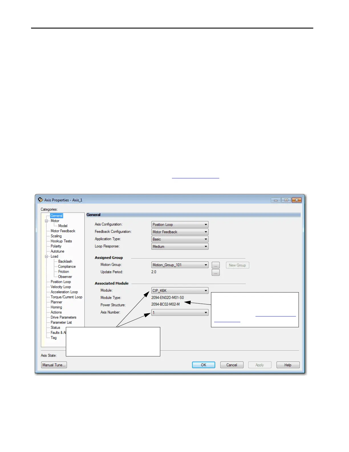
2. From the Axis Configuration pull-down menu, choose Position Loop.
3. From the Feedback Configuration pull-down menu, choose Dual
Feedback.
The axis and feedback configurations determine the control mode.
For more information on the control modes, see the Integrated Motion
on the EtherNet/IP Network Reference Manual,
publication MOTION-RM003
.
Figure 27 - Example 2: Position Loop with Dual Feedback, General Dialog Box
The type of drive you selected and the power
structure you assigned via the Kinetix 6500 Module
Properties.
For more information, see Add a Kinetix EtherNet/IP
Drive on page 32.
The newly created Kinetix 6500 drive module name is
the default. The Axis Number defaults to 1, indicating
the primary axis of the drive. Axis Number 2 is used only
for configuring a Feedback Only axis.

 Loading...


