Rockwell Automation Publication MOTION-UM003K-EN-P - January 2019 69
Configure Integrated Motion Control Using Kinetix 5700 Drives Chapter 4
Continue Inverter Configuration
After you have established your Kinetix 5700 inverters in the Logix Designer
application, the feedback options must be defined for each axis. Each physical
axis supports motor and auxiliary feedback.
Table 15 - Kinetix 5700 Feedback Axis Summary
Follow these steps to configure the axes for your Kinetix 5700 drive system.
1. Right-click the 2198-xxxx-ERS4 inverter that you just created and
choose Properties.
The Module Properties dialog box appears.
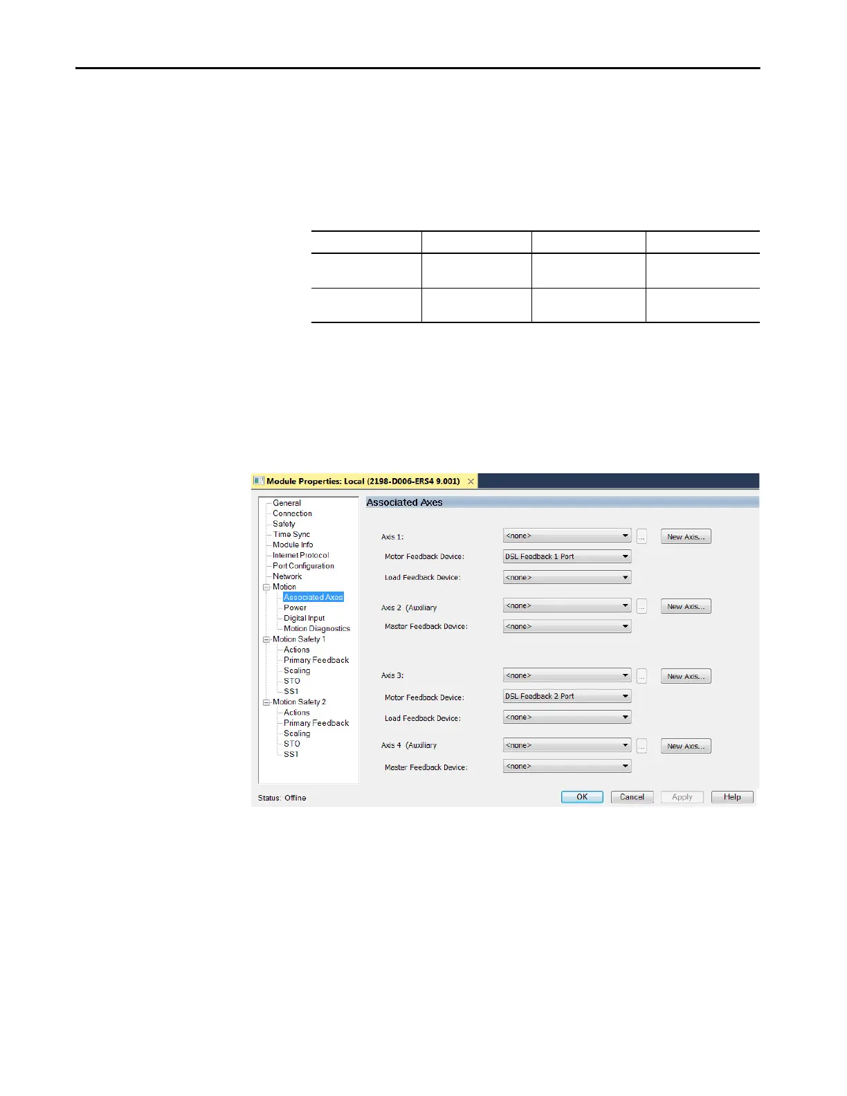
2. Select the Associated Axes category.
In this 2198-D006-ERS4 (dual-axis inverter) example, four axes are
possible. Single-axis inverters support only two axes.
• Axis 1 and Axis 2 apply to Motor (DSL) Feedback Connector A
(Port 1) and Universal Feedback Connector A (Port 1).
• Axis 3 and Axis 4 apply to Motor (DSL) Feedback Connector B
(Port 2) and Universal Feedback Connector B (Port 2).
Kinetix 5700 Inverter Inverter Cat. No. Motor Feedback Auxiliary Feedback
Single-axis Inverters
2198-Sxxx-ERS3 or
2198-Sxxx-ERS4
1 (axis 1) 1 (axis 2)
Dual-axis Inverters
2198-Dxxx-ERS3 or
2198-Dxxx-ERS4
2 (axis 1 and 3) 2 (axis 2 and 4)

 Loading...


