INTRODUCTION
The DGS-1100-16/ME consists of 16-ports 10/100/1000Mbps.
The DGS-1100-18/ME consists of 16-ports 10/100/1000Mbps ports + 2-ports 1000Mbps SFP
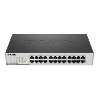
The DGS-1100-24/ME consists of 24-ports 10/100/1000Mbps.
The DGS-1100-24P/ME consists of 12-ports 10/100/1000Mbps PoE + 12-ports 10/100/1000Mbps.
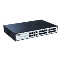
The DGS-1100-26/ME consists of 24-ports 10/100/1000Mbps + 2-ports 1000Mbps SFP.
The Switch can be managed through the Telnet management agent. The Command Line Interface (CLI)
can be used to configure and manage the Switch via the Telnet interfaces.
This manual provides a reference for all of the commands contained in the CLI. Configuration and
management of the Switch via the Telnet interfaces is discussed in the Manual. For detailed information
on installing hardware please refer also to the Manual.
Setting the Switch’s IP Address
Each Switch must be assigned its own IP address, which is used for communication with an SNMP
network manager or other TCP/IP application (for example BOOTP, TFTP). The Switch’s default IP
address is 10.90.90.90. You can change the default Switch IP address to meet the specification of your
networking address scheme.
The Switch is also assigned a unique MAC address by the factory.
The Switch’s MAC address can also be found in the Telnet interfaces by entering show switch.
The IP address for the Switch must be set before it can be managed with the Telnet interfaces. The Switch IP
address can be automatically set using BOOTP or DHCP protocols, in which case the actual address assigned
to the Switch must be known.
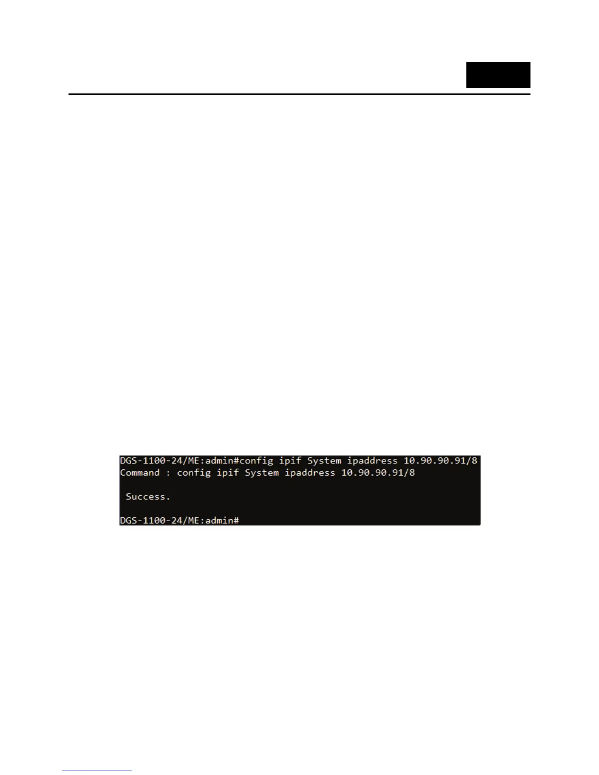
Alternatively, users can enter config ipif System ipaddress xxx.xxx.xxx.xxx/z. Where the x’s represent the IP
address to be assigned to the IP interface named System and the z represents the corresponding number of
subnets in CIDR notation.
The IP interface named System on the Switch can be assigned an IP address and subnet mask which
can then be used to connect a management station to the Switch’s Telnet management agent.
Figure 1–1 Assigning an IP Address
In the above example, the Switch was assigned an IP address of 10.90.90.91 with a subnet mask of
255.0.0.0. The system message Success indicates that the command was executed successfully. The
Switch can now be configured and managed via Telnet, SNMP MIB browser and the CLI using the above
IP address to connect to the Switch.
1
 Loading...