80209C_MHW_850-1650-1850_02-2020_ENG_pag. 100
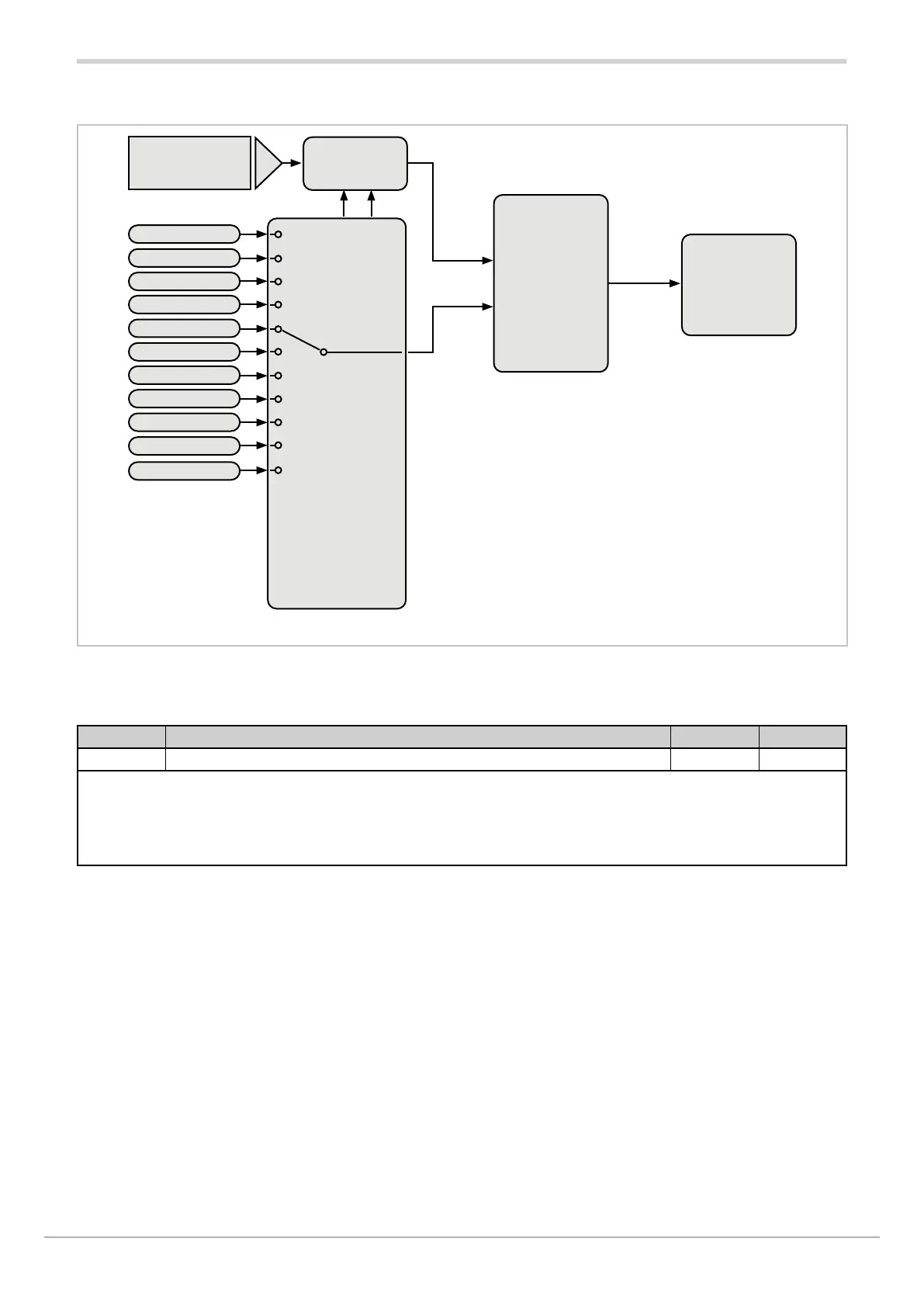
4.11.1. Functional diagram
4.11.2. ALARM -Selecting the alarm to be configured
Acronym Scrolling message Submenu Attributes
ALRM.N ALARM NUMBER ALARM R W
The parameter shows and sets the alarm to be configured, identified by its number.
Unit of measurement: Number
Options: 1...ALRM.N = Identifying number of alarm, where ALRM.N is the total number of alarms, setting
by submenu MODE..
Alarm
type
DI.IN page. 51
AB.RE page. 102
NO.SY page. 102
PWON.E page. 102
LATCH page. 103
Hysteresis
HYSTE page. 103
Delay
DELAY page. 103
Blinking
display
BLK.AL page. 104
Scrolling
message
MSG.AL page. 103
Alarm threshold
ALRMx
Control
limits
of scale
Reference variable
selection
REFE page. 101
Alarm threshold
scale limits
LO.AL page. 94
HI.AL page. 94
HI.SCL page. 93
Alarm
state
(ALRMx)
Value
Threshold
MaxMin
PV1/PV2
IN1/IN2/IN3
SSP1/SSP2
CURR1
CURR2
OU.KW1/OU.KW2
O.KWH1/O.KWH2
E.KWH1/E.KWH2
P.DAYS
T.INT
MAS.xx (*)
(*) xx =da 01 a 20

 Loading...


