80209C_MHW_850-1650-1850_20-2020_ENG_pag. 19
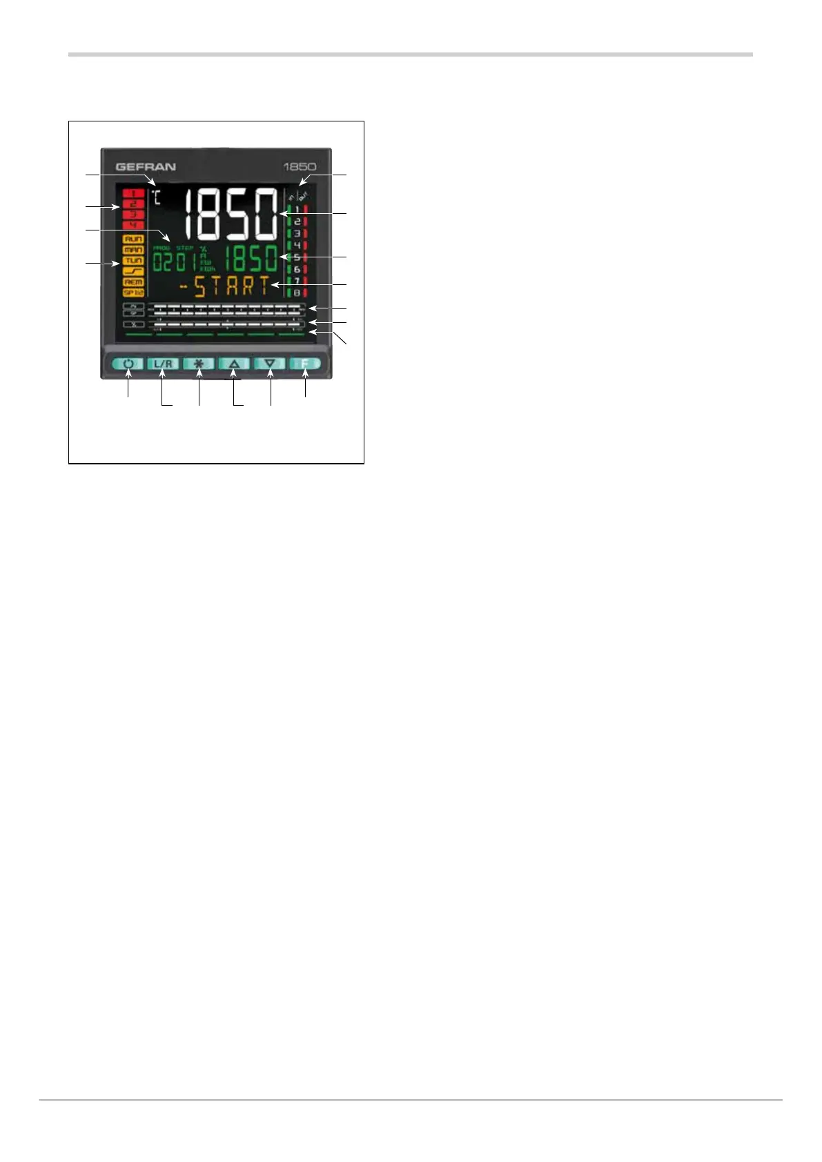
1.5.1. Display and keys
2
1 15
3
5 8 7 6
14
11
10
9
13
12
4
1
Unit of measurement or number of program running or number of
loop displayed.
2
State of outputs OUT1, OU2, OUT3, OUT4.
3
Displays program number, step number, unit of measurement
(%, A, kW, kWh).
4
Controller function states:
● RUN = functioning (flashing = normal functioning, steady
on = program running);
●_/- = setpoint ramp active;
●TUN = PID parameters tuning active;
●MAN = manual/automatic (off=automatic control, on = manual control);
●REM = remote setpoint enabled;
●SP1/2 = setpoint active (off = setpoint 1, on = setpoint 2).
5
Work mode key (manual/automatic) in standard mode. A function
can be assigned via parameter but1. The key is active only when
the display shows the process variable.
6
Key function configurable with parameters but2 and but3. The keys
are active only when the display shows the process variable (HOME).
7
Up/down keys: raise/lower the value of the parameter displayed on
the SV or PV display.
8
F key: lets you navigate among controller menus and parameters.
Confirms the parameter value and selects the next parameter.
9
Key pressed signals.
Figure 5 - Description of 1850 display and keys
10
Displays percentage of power or current, configurable with parameter
bAr3.
11
Display of percentage of process variable and of setpoint
12
F display: parameters, diagnostics and alarm messages.
Configurable with parameter dS.F (default = % control power).
13
SV display: parameter values. Configurable with parameter dS.SP
(default = setpoint).
14
PV display = Process variable
15
Display of inputs/outputs state (only with 8 INS/OUTS and/or 8 relays).

 Loading...


