80209C_MHW_850-1650-1850_01-2020_ENG_pag. 193
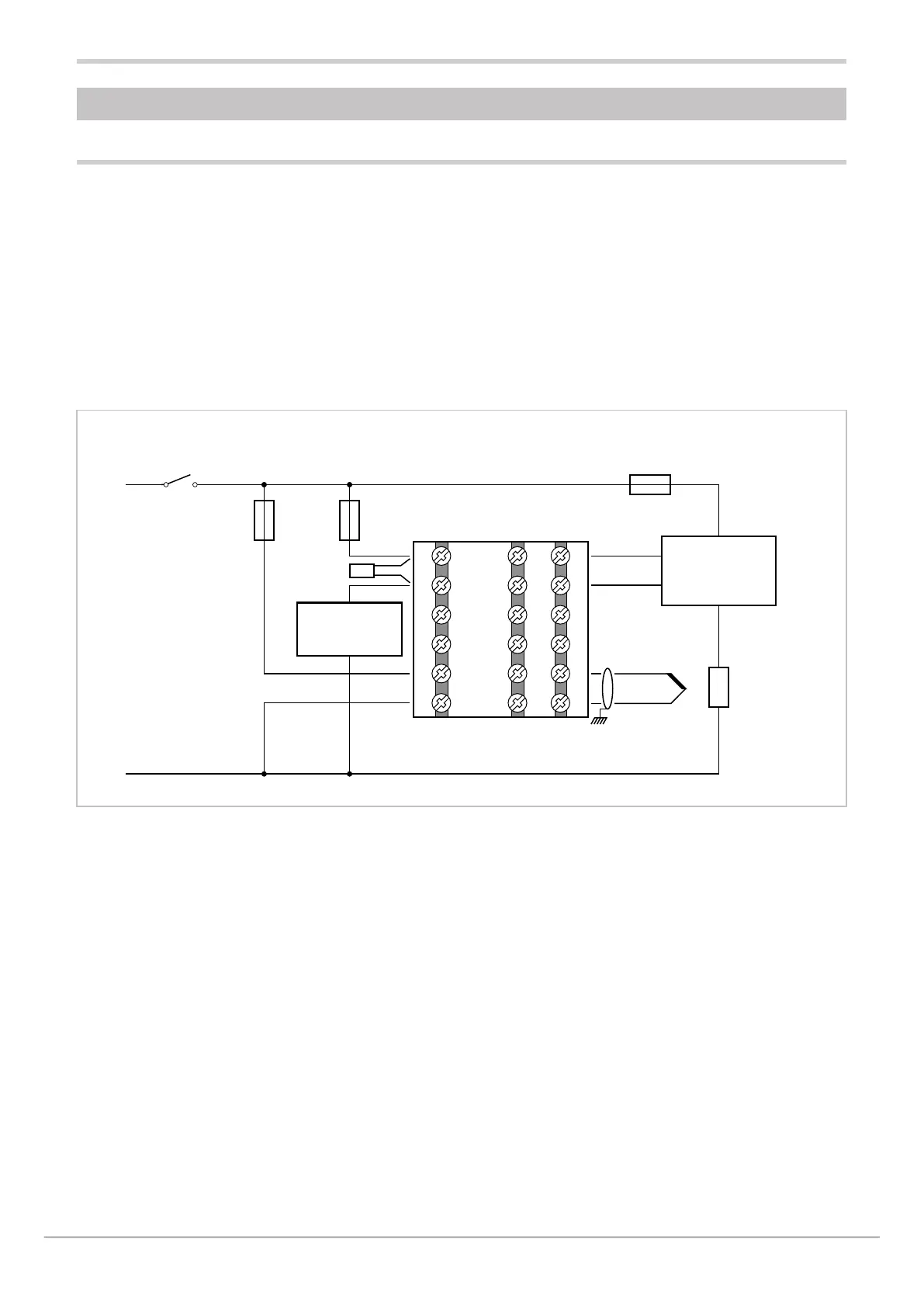
5.1.1. Connection diagram
6
5
4
3
2
1
7
8
9
10
11
12
19
20
21
22
23
24
+
-
T/C
Heating element
fuse
Solid state
relay
Heating
element
Fuse relay cooling
or alarm
Controller
fuse
Coolingor
alarm relay
850 Controller
Snubber
5. EXAMPLES AND APPLICATION NOTES
5.1. Heat/cool control application
A 850 controller (model 850–D-R00-00000-1) controls a
heating element via a solid-state relay connected to a
logic output.
A TC sensor measures the temforature.
Each branch of the circuit is protected by a fuse.
The cooling or alarm relay is protected by a snubber.
The following diagram shows the various connections.
One switch can control more than one controller.
• With Quick Configuration you set:
• sensor type (TC);
• unit of measurement of temforature (°C);
• the logic output function (HEAT);
• the relay output function (ALRM1);
• the full-scale value of the CT1 current transformer
• (HI.CT1)
• the setpoint, i.e. the temforature to be maintained (SETP);
• the temforature value that trips the alarm (ALRM1).

 Loading...


