80209C_MHW_850-1650-1850_20-2020_ENG_pag. 23
2.2. Connections
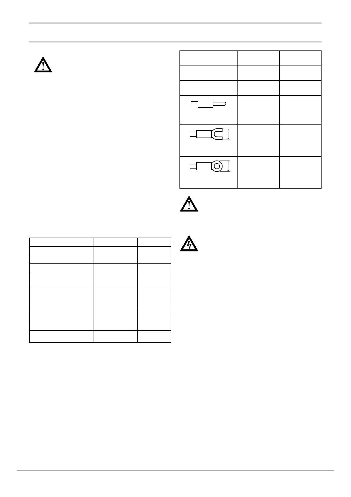
Cable / terminal
Cable / termi-
nal section
Terminal size
Rigid cable 0,8...2,5 mm
2
(18...14 AWG)
Twisted 0,8...2,5 mm
2
(18...14 AWG)
Tag terminal
(to be crimped)
0,25...2,5 mm
2
(23...14 AWG)
5,8
Fork terminal
(to be crimped)
5,8 mm max
5,8
Ring terminal
(to be crimped)
5,8 mm max
Attention! Anchor the cables, at least in pairs, so
that mechanical stresses do not discharge on the
terminal connections.
2.2.4. Power supply
Attention! Before powering the controller, make
sure that the supply voltage matches the one
shown on the controller data plate.
Because the controller does not have a switch, a bipolar
switch with fuse must be inserted upline. The switch, or
isolator, must be positioned in the immediate vicinity of the
device and must be easily reached by the operator.
A single switch can control multiple controllers.
The controller must be powered by a line separated from
the one used for electromechanical power devices (relays,
contactors, solenoids, etc).
It is advisable to install a ferrite core on the power line,
as close as possible to the device, to limit the controller’s
susceptibility to electromagnetic noise.
If the controller’s power line is heavily disturbed by the
switching of thyristor power units or by motors, it is advisable
to use an isolation transformer only for the controller,
grounding the shield.
Use appropriate line filters in the vicinity of high-frequency
generators or arc welders.
Use a voltage stabilizer if there are wide shifts in line voltage.
20...27 VAC/VDC models must be powered by a class II or
low-voltage limited-energy source.
The power supply must use a line separated from the one
used for electromechanical power devices, and low-voltage
power cables must run along a path separated from the
system or machine power cables.
Attention! Failure to follow the instructions in
this section may cause problems in electrical
safety and electromagnetic compatibility, in
addition to voiding the warranty.
2.2.1. General rules for connections
1. Connected external circuits must have double isolation.
2. In case of shielded cables, the shield must be grounded
at a single point, possibly near the controller.
3. Input cables must be physically separated from power
cables, output cables, and power connections.
4. Do not connect unused terminals.
5. Tighten the terminals without forcing. Loose terminals
may cause sparks and fires.
The recommended tightening torque is 0.5 Nm.
6. When making connections, respect polarity where
required.
7. Do not bend or twist the cables beyond the limits
specified by the manufacturers.
8. After connecting the cables, apply the transparent cover
to protect the terminals.
The terminal teeth limit and define the correct direction
for applying the cover.
2.2.2. Electromagnetic compatibility (EMC)
For electromagnetic conformity, the strictest general rules
have been applied, using the following test configuration:
Connection Cable section Length
Power supply
1 mm
2
1 m
Relay
1 mm
2
3,5 m
Serial port
0,35 mm
2
3,5 m
Thermocouple
0,8 mm
2
5 m
compensated
Potentiometer, linear,
“PT100” resistance
thermometer
1 mm
2
3 m
Analog retransmission
output
1 mm
2
3,5 m
Digital input/outputs
1 mm
2
3,5 m
Ethernet port
UTP 4x2xAWG24
cat 6
4 m
2.2.3. Cables
Always use cables appropriate for the voltage and current
limits specified in the Technical Characteristics.
Use copper cables with 60/75°C insulation.
Use twisted and shielded cables for non-power connections.
The controller’s terminal board has screw terminals (M3) that
accept stripped cables and crimped terminals for a tighte-
ning torque of 0.5 N m.
Two ring or crimped fork terminals can be connected on
each terminal
The following table shows the characteristics of the cables
and terminals that can be used.

 Loading...


