80209C_MHW_850-1650-1850_01-2020_ITA_pag. 278
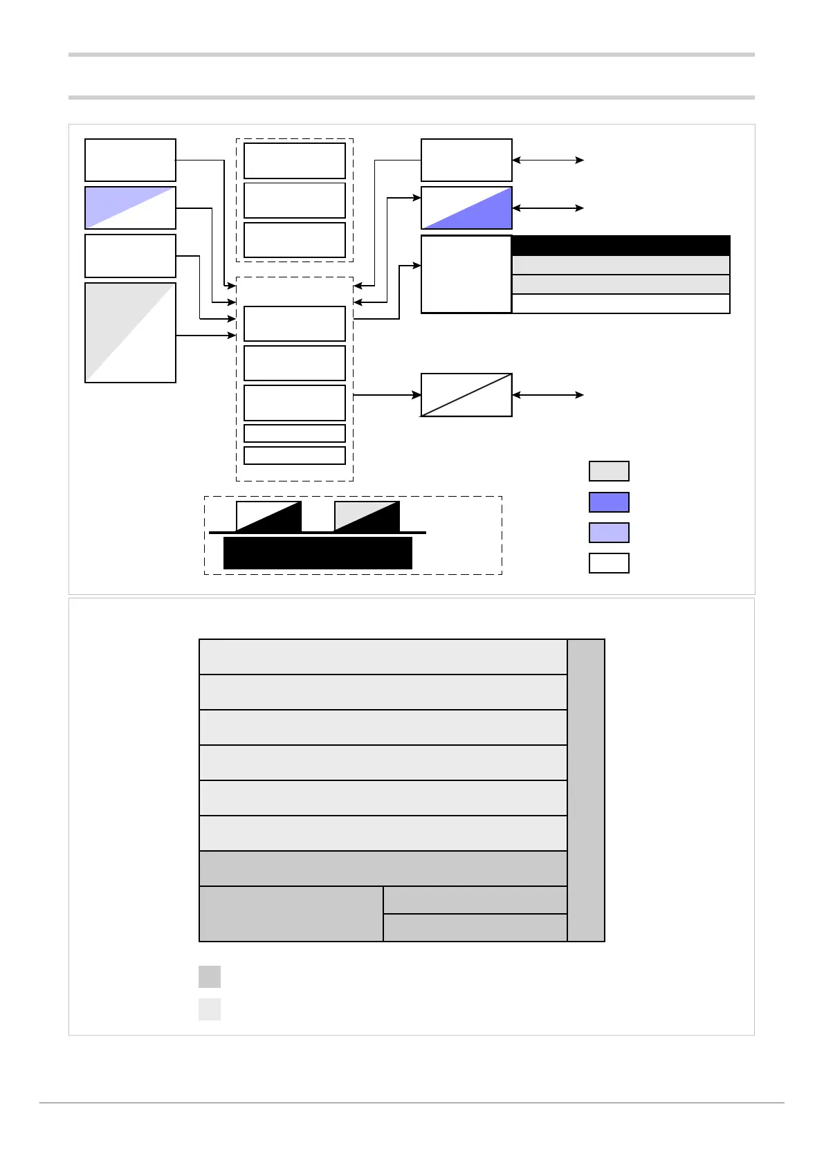
9.4. Isolation block diagram 850
+24 V
+5 V
3,3 V Auxiliary Input
+3,3 V
SENSOR
INPUT
PV
AUXILIARY
INPUT
DIGITAL INPUT
DI1...DI3 or
TRANSMITTER
POWER
SUPPLY
CT1, CT2
INPUT
LCD +
CONTROLLER
BACK LIGHT
4 keys
CONFIGURATION
PORT
COMMUNICATION
INTERFACE
OUT 1, 2, 3, 4
LOGIC OUTPUT (SSR drive)
DC OUTPUT
TRIAC, RELAY, MOS
POWER IN
(90...260 VAC / 18...30 VAC/VDC)
CPU
Main Processor ARM
FLASH memory
FRAM
FIELDBUS
PC INTERFACE
POWER
SUPPLY
Internal Temperature
RTC
SRAM
Modbus
TCP
FIELDBUS
OUT1 G (Master Modbus)
Functional isolation
Reinforced isolation
Sensor input, CT Input, Configuration port
Transmitter power supply (VT1)
Auxiliary input (PV2), Transmitter power supply (VT2)
Potentiometer power supply (VP)
Fieldbus
communication interface
Ethernet
communication interface
Digital input, Logic output (SSR drive), DC output 1,
Analog DC output 1, DC output A1
MOS digital output
Relay output 1
Relay outputs 2, 3, 4
Relay output 2
Relay or Triac output 3
Power supply
100...240 VAC/VDC / 20...27 VAC/VDC

 Loading...


