80209C_MHW_850-1650-1850_01-2020_ENG_pag. 198
Note1: you do NOT need to remember to disable linearisation
during the procedure
Note2: you do NOT need to remember to reset the offset
WARNING: if the FILT.D parameter is not 0, when you return
to the home page, you may find a PV value different from
the one set (as the INx parameter is displayed during the
procedure, and not PVx ). In the LINRZ menu, on the other
hand, the PV for compatibility with the old linearisation
method appears.
5.4.1. Entering linearisation parameters with the
LINRZ menu
The four values may be entered directly in the LINRZ menu,
as follows:
• X1 = STP.00
• X2 = STP.01
• Y1 = STP.02
• Y2 = STP.03
In this case, however, you must obligatorily reset the
OF.SCLx parameter if it is included in the INPUT menu,
and disable 4-point linearisation so that the LINRZ menu
displays the input value without the contribution of offset
and linearisation.
Example
Selection of Pt100 input with Lin = 4.POIN to obtain an RTD
sensor with 4-point input correctio.
Pt100 input with:
• Lin = 4.POIN (Pt100 natural scale -200...850),
• DEC.P = 0
• LO.SCL = 0
• HI.SCL = 400
X1 = 50
Y1= 120
Y2= 220
X2 = 350
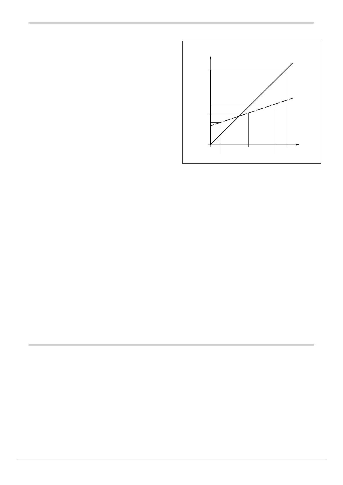
0
0
400
400
200
170
Without
correction
With
correction
Input
Indication
Figure 20 - Diagram of 4-point input correction, for the
example (Pt100 input)
5.5. Current inputs
The values of current inputs CT1 and CT2 are shown in
parameters CURR1 and CURR2.
These values are used in generic alarms AL1… AL4 and
especially for the HB alarm
The maximum scale value of the input is shown by parameter
HI.CT1 on submenu I.CT1 for CT1, and by parameter HI.CT2
on submenu I.CT2 for CT2
The reference points on the real curve (input) are:
• X1 = STP.00 = 50,
• X2 = STP.01 = 350,
X2-X1 = 300, which is 85 more (10% of 850).
The corresponding points on the corrected curve (indication) are:
• Y1 = STP.02 = 120,
• Y2 = STP.03 = 220.
With the corrected curve, an input value of 200 is displayed
as 170.

 Loading...


