80209C_MHW_850-1650-1850_02-2020_ENG_pag. 110
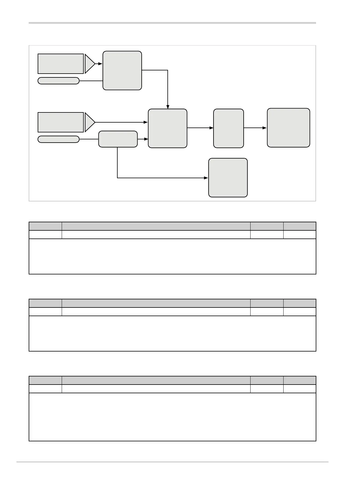
4.13.1. Functional diagram
Blinking
display
BLK.PW page. 111
Scrolling
message
MSG.PW page. 111
Stability band
PV
PW.BND page. 110
Power
stability band
PW.BND page. 110
Stato
AL.PWx
Stability
state
power
Average power
Stability
State
PV
PV.x
OUT.Px
Delay
TIME
page. 111
Stability
control
power
automatically
power
PV in error
Stability
control
PV
Media
4.13.2. AL.PW - Select the Power alarm to configure
Acronym Scrolling message Submenu Attributes
AL.PW.N POWER ALARM NUMBER AL.PW R W
The parameter shows and sets the alarm to be configured, identified by its number.
Unit of measurement: Number
Options: 1 = Select alarm referring to PID.1
2 = Select alarm referring to PID.2 (only with auxiliary input option)
4.13.3. PV.BND – Process variable stability band
Acronym Scrolling message Submenu Attributes
PV.BND AL.PW.1 (or AL.PW.2) PV STABILITY BAND AL.PW R W
The parameter shows and sets the value of the process variable stability band within which the alarm is assessed.
If the parameter is “0.0” the power alarm is disabled.
Unit of measurement: %
Options: 0.0...100.0
4.13.4. PW.BND – Power stability band
Acronym Scrolling message Submenu Attributes
PW.BND AL.PW.1 (or AL.PW.2) PW STABILITY AL.PW R W
The parameter shows and sets the value of the power stability band. When the process variable is in PV.BND stability
band and average power exits PW.BND power stability band, the alarm activates after TIME. When the power alarm is
active, it is automatically cancelled if the setpoint is changed, or by setting parameter AL.ACK = On on the user configu-
ration menu, or by switching to Manual mode.
Unit of measurement: %
Options: 0.0...100.0

 Loading...


