80209C_MHW_850-1650-1850_20-2020_ENG_pag. 30
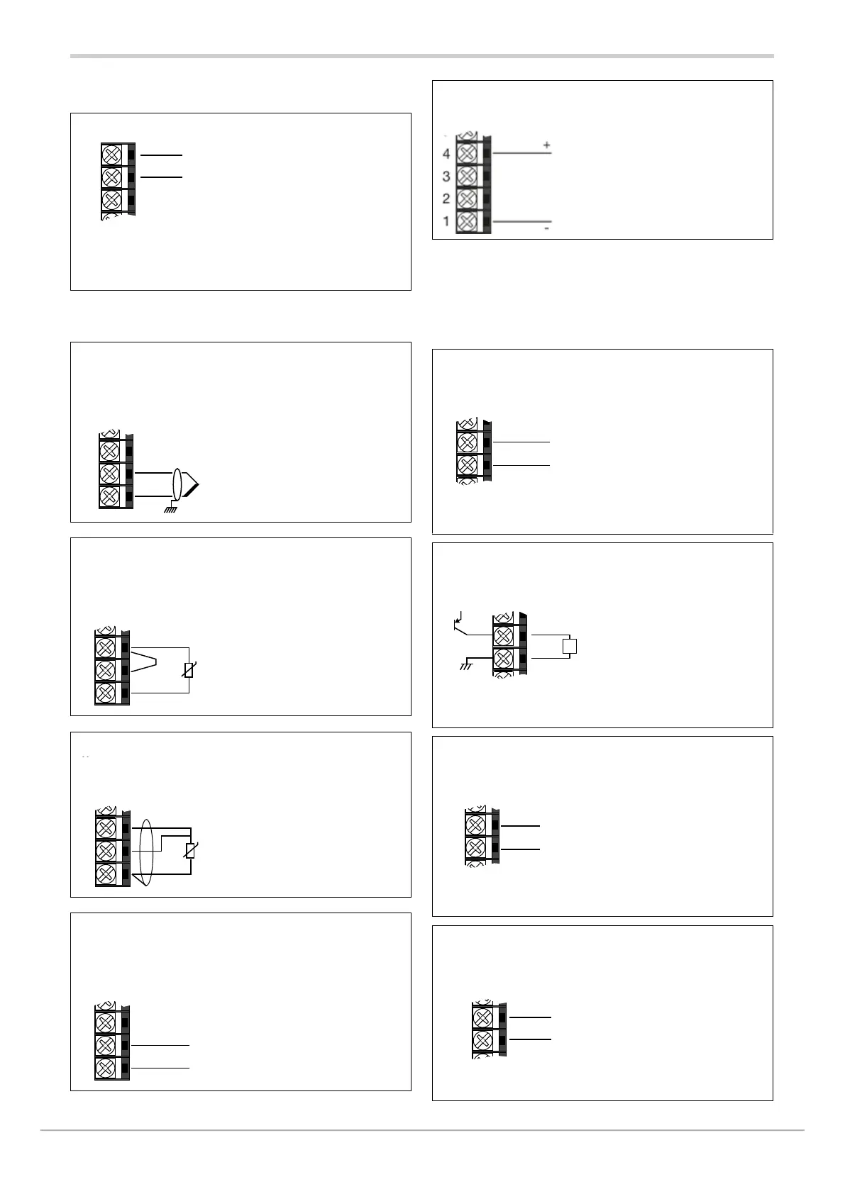
2.4.2. Power supply
Power supply
12
11
10
22
23
24
~
~
PWR
Standard:
100...240 VAC/VDC ± 10%
50/60 Hz, max 10W
Optional:
20...27 VAC/VDC ± 10%
50/60 Hz, max 10W
(*) ground connection for option
20...27 V AC/DC only
2.4.3. Main input (MAIN)
TC Input
6
5
4
3
2
1
+
-
Available thermocouple:
J, K,R, S, T, C, D B, E, L, L-GOST,
U, G, N, Pt20Rh-Pt40Rh
ITS90 or custom linearization
Respect polarity
For extensions, use a compensated
cable
Input PT100/JPT100 - 2-wires connection
6
5
4
3
2
1
T
Attention:
with this type of connection the line
resistance can introduce measurement
error, we recommend that you use
wires of adequate screen.
Input PT100/JPT100 - 3-wires connection
5
4
3
2
1
T
Attention:
with this type of connection the line
resistance can introduce measurement
error, we recommend that you use
wires of adequate screen.
The resistance of the three wires must
be equal, the line resistance must be
less than 20 ohm.
Linear input (V, I)
6
5
4
3
2
1
+
-
Linear input in direct voltage
0...60 mV
0...1 V Ri
Linear input in direct current
0/4...20mA, Ri = 50 Ω.
Linear input (V)
Linear input in direct voltage
0...5 V / 0...10 V Ri > 400kΩ
2.4.4. Outputs
Characteristics of outputs Out1, Out2, Out3, Out4 are
defined when the controller is ordered.
Outputs Out 1 - relay 5 A
6
5
5
3
NO
C
Relè 250 VAC, 5 A
Outputs Out 1 - logic
6
5
+
-
L
+V
Logic 24 V ±10%
(min 10 V a 20 mA)
Outputs Out 1 - continuous
6
6
5
3
2
+
-
4...20 mA Rout < 500 Ω
Outputs Out 2 – relay 5 A
19
20
8
7
23
24
NO
C
Relay 250 VAC, 5 A

 Loading...


