80209C_MHW_850-1650-1850_20-2020_ENG_pag. 34
2.5. 1850 connection diagrams
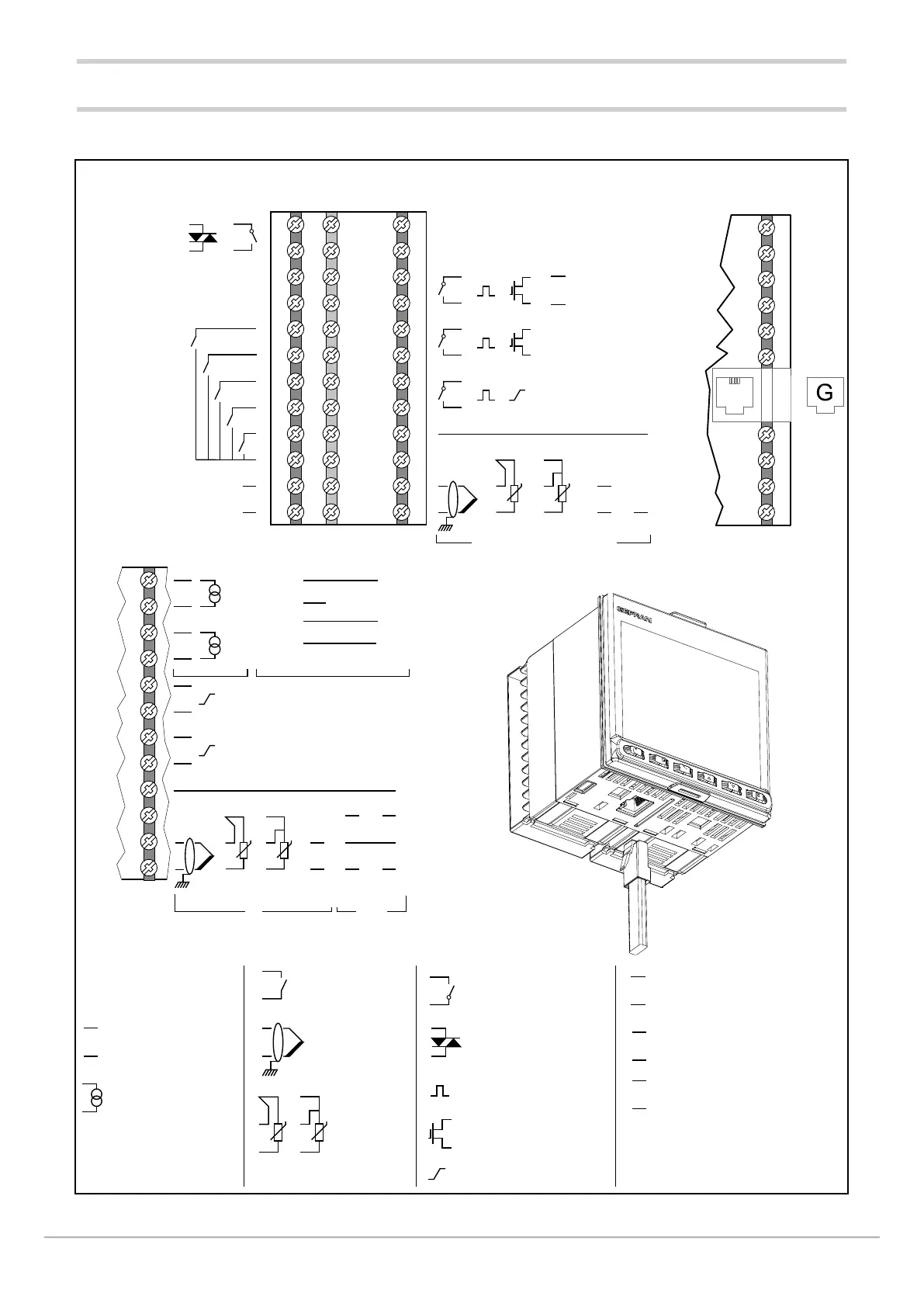
2.5.1. General diagram
-
37
38
39
40
41
42
12
11
10
9
8
7
6
5
4
3
2
1
43
44
45
46
47
48
36
35
34
33
32
31
30
29
28
27
26
25
36
35
34
33
32
31
30
29
28
27
26
25
+
-
TT
+
-
+
-
CT1
CT2
OUT A2
OUT A1
+
-
~
PWR
~
+
-
+
-
C
+
-
TT
+
-
+
-
C
NO
5 V, 10 V
60 mV, 1 V, 20 mA
OUT 1
+
-
C
NO
OUT 2
C
NO
OUT 3
+
-
~
~
A (Data -)
B (Data +)
C
NO
IN 1
IN 2
IN 4
IN 5
IN 3
COM
OUT 4
+ +
-
+
+
-
VP1 VT2
1 V, 20 mA
5 V, 10 V
60 mV
+
-
VT1
= 1 = 2 o 3
T
T
NO
C
+
-
~
~
+
-
+
+
-
~
PWR
~
B (Data +)
A (Data -)
+
-
VT
+
-
VP
12
11
10
9
8
7
6
5
4
3
2
1
-
Current transformer
second current transformer
for 2-phase /3-phase load
Main input (Main)
Auxiliary input
for model with option auxiliary input (Aux1)
LEGEND
Power supply
Linear input in
voltage / current
Supply
transmitter
Supply
potentiometer
Input for
current
transformer
Relay output
Long-life solid state
relay output
Isolated analog output
Isolated digital
inputs
RS485 serial line
Logic output
Isolated logic output
Thermocouple
input
Input
PT100
JPT100
2 / 3wires
Option
Modbus RTU
(M) = M0
communication
or ME
+
5V, 10V, 20mA,
Option CT (H) = 2
1V, 1.2V, 2.4V, high impedance
VP2
+
+
+
With Ethernet communication option(M) = E0 or ME
Optional third input AUX2 (H) = 3
with option OUT1
Master Modbus (B) = G

 Loading...


