80209C_MHW_850-1650-1850_20-2020_ENG_pag. 42
4
3
2
1
45
46
47
48
28
27
26
25
4
3
2
1
45
46
47
48
28
27
26
25
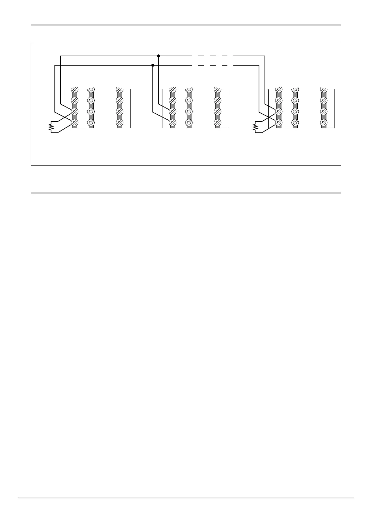
120 Ω
1/2 W
+
-
+
-
1650 - 1850
1650 - 1850
4
3
2
1
45
46
47
48
28
27
26
25
Ω
+
-
1650 - 1850
Figure 17 - RS485 bridge connection of controllers 1650 and 1850 with communication option (M) = ME
2.7. Ethernet port wiring diagram
Controllers 850, 1650 and 1850 may, on request, be equip-
ped with an Ethernet 10/100BaseT port with direct con-
nection via RJ45 connector.
For this connection, use a type UTP cable of category 5
or greater, crimped with a standard non-shielded RJ45
connector.
The instrument automatically recognises the polarity of the
cable used, and so you may use either a straight or a cross
cable equally well for point-to-point connections with a PC
or to a switch.
The maximum connection length supported is 100m, accor-
ding to standard IEEE 802.3u; if segments longer than 100
m are required, insert signal repeaters (switches) to break
up the network.
Connector RJ45 has two signal and diagnostics LEDs:
- Amber LED: when steady on, indicates the presence of
the signal carrier (link)
- Green LED: when flashing, indicates data exchange
underway on port (activity).

 Loading...


