Table 77 on page 138 shows the pin assignments of the RJ-45 cable that connects to two
RJ-11 connectors.
Table 77: RJ-45 Cable (RJ-45 to Two RJ-11 Connectors) Pinout Details
Signal
Plug 2
Signal
Plug 1
RJ-11 Pin
NumberSignal
RJ-45 Pin
Number
-Tip 1 of 1st port2Tip 11
-Ring 1 of 1st port5Ring 12
Tip 2 of 2nd port-3Tip 23
-Tip 0 of 1st port3Tip 04
-Ring 0 of 1st port4Ring 05
Ring 2 of 2nd
port
-4Ring 26
Tip 3 of 2nd port-2Tip 37
Ring 3 of 2nd
port
-5Ring 38
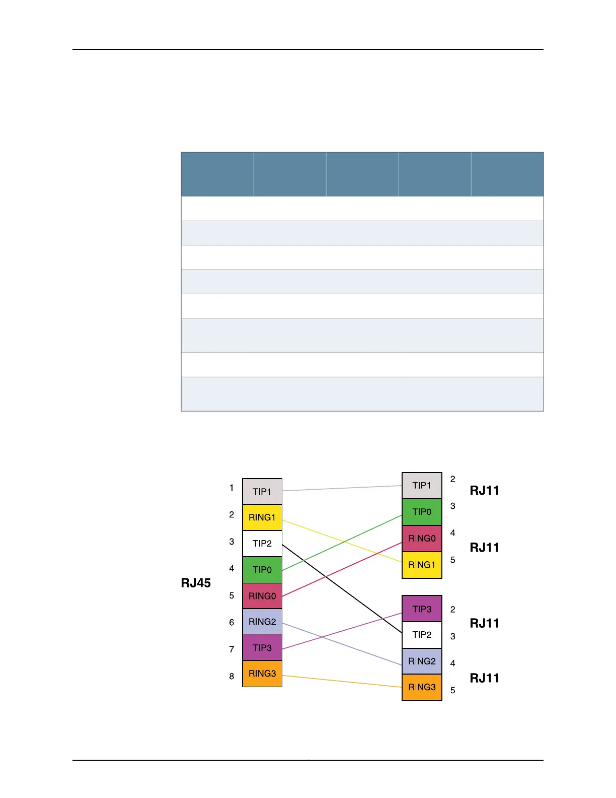
Figure 37 on page 138 shows the RJ-45 cable design that connects two RJ-11 cable
connections.
Figure 37: RJ-45 Cable Design (RJ–45 to Two RJ-11 Connectors)
Standard RJ-45 Cable Pin Assignment
Copyright © 2015, Juniper Networks, Inc.138
SRX Series Services Gateways for the Branch Physical Interface Modules Reference
 Loading...