circuit-terminating equipment (DCE). Different cables are required to support different
protocol and the protocols are identified using the cable ID. The cables are labeled with
a letter (refers to the cable type) and 4 digits (unique serial numbers for the cables).
Table 91 on page 162 lists the cables supported by 8-Port Serial GPIMs. You can order the
cables from Juniper Networks to connect to a port on the synchronous 8-Port Serial
GPIM. The device to which you are connecting and the serial interface types determine
which type of cable you need.
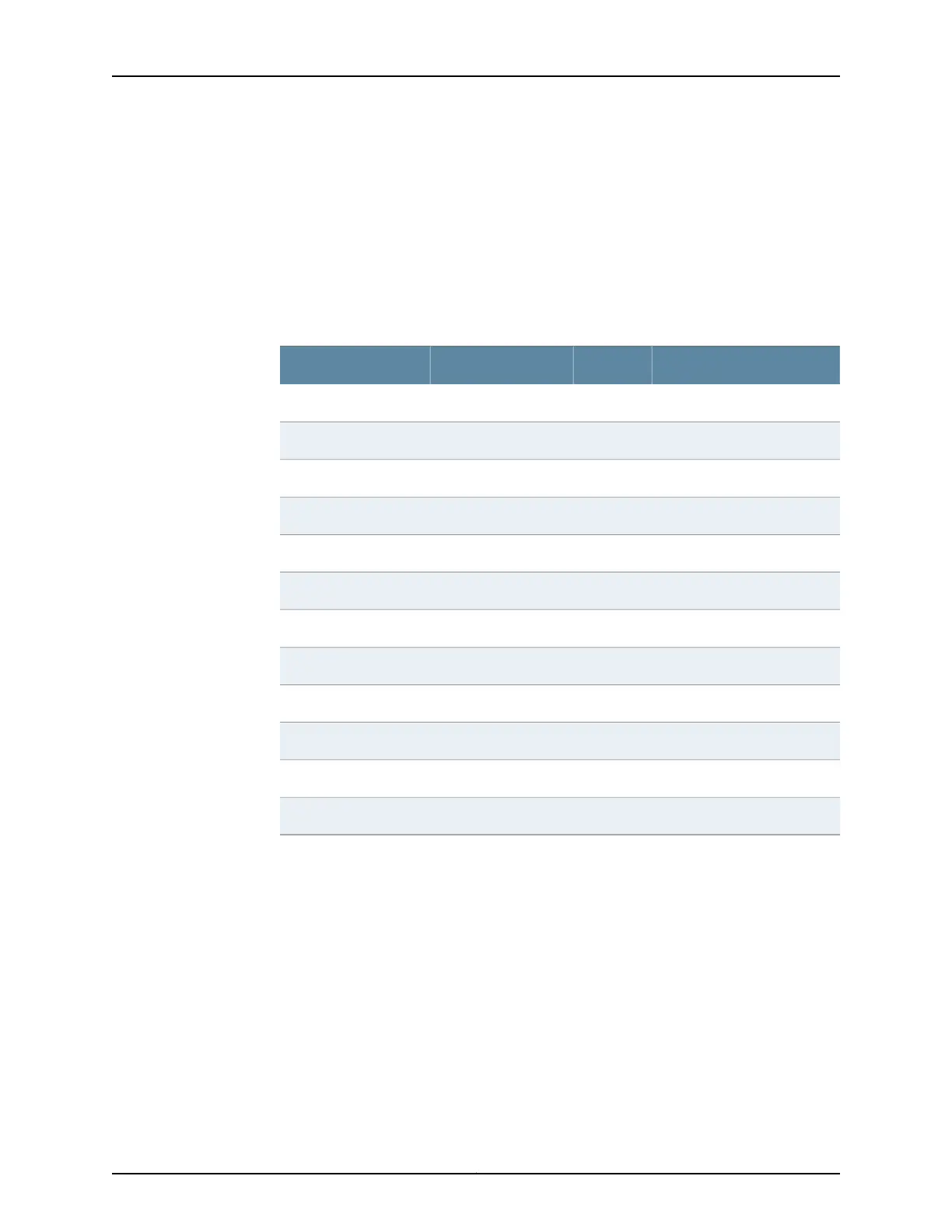
Table 91: Juniper Networks Supported Cables
Connector TypeLetterInterface TypeProduct Number
MaleCRS-232 cable (DTE)SRX-CBL-RS232-DTE-2
FemaleDRS-232 cable (DCE)SRX-CBL-RS232-DCE-2
MaleEV.35 cable (DTE)SRX-CBL-V35-DTE-2
FemaleFV.35 cable (DCE)SRX-CBL-V35-DCE-2
MaleGEIA-449 cable (DTE)SRX-CBL-EIA449-DTE-2
FemaleHEIA-449 cable (DCE)SRX-CBL-EIA449-DCE-2
MaleIEIA-530A cable (DTE)SRX-CBL-EIA530A-DTE-2
FemaleJEIA-530A cable(DCE)SRX-CBL-EIA530A-DCE-2
MaleKX.21 cable (DTE)SRX-CBL-X21-DTE-2
FemaleLX.21 cable (DCE)SRX-CBL-X21-DCE-2
MaleMEIA-530 cable (DTE)SRX-CBL-EIA530-DTE-2
FemaleNEIA-530 cable (DCE)SRX-CBL-EIA530-DCE-2
Figure 39 on page 163 shows the cables with name A and B at the serial connector end.
Label A refers to port 0, port 2, port 4, or port 6 and label B refers to port 1, port 3, port 5,
or port 7 depending on which port the cable is connected.
Copyright © 2015, Juniper Networks, Inc.162
SRX Series Services Gateways for the Branch Physical Interface Modules Reference
 Loading...