FX3U Series Programmable Controllers
User’s Manual - Hardwaer Edition
109
6 Examination of System Configuration
6.9 Example of System Configuration and System Modification
1
Introduction
2
Features and
Part Names
3
Product
Introduction
4
Specifications
5
Version and
Peripheral
Devices
6
System
Configuration
7
Input/Output
Nos., Unit Nos.
8
Installation
9
Preparation and
Power Supply
Wiring
10
Input Wiring
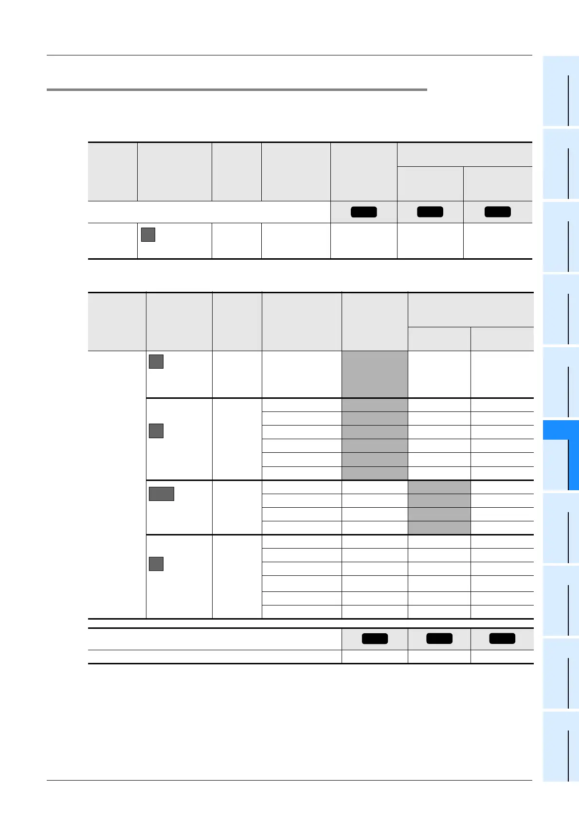
6.9.2 Expansion of main unit
The suitability of the above system configuration is evaluated as shown below.
1 Enter the specifications for the main unit.
2 Enter the specifications for the products to be connected to the main unit.
*1. The number for FX2N-64CL-M is calculated by adding the number of input/output points at the
connected remote I/O station to 8 points.
Classification
Number of
connected
units
Type
Number of
input/output
points [points]
Capacity of built-in power
supply
5V DC power
supply [mA]
24V DC service
power supply
[mA]
With built-in
power
supply
Main unit
1FX
3U-48MR/ES 48 500 600
Classification
Number of
connected
units
Type
Number of
input/output
(occupied)
points [points]
Calculation of current
consumption of built-in
power supply
5V DC power
supply [mA]
24V DC power
supply [mA]
Enter the
products
connected to
the main unit.
Expansion
board
1FX
3U-232-BD − 20 0
Special adapter
6
FX
3U-4HSX-ADP − 30 30
FX
3U-2HSY-ADP − 30 60
FX
3U-2HSY-ADP − 30 60
FX
3U-485ADP − 20 0
FX
3U-4AD-ADP − 15 0
FX
3U-4AD-ADP − 15 0
Input/output
extension block
4
FX
2N-16EX-ES/UL 16 − 100
FX
2N
-16EYT-ESS/UL
16 − 150
FX
2N-16EX-ES/UL 16 − 100
FX
2N
-16EYR-ES/UL
16 − 150
Special function
unit/block
6
FX
2N-1HC 8 90 0
FX
2N-10PG 8 120 0
FX
2N-2LC 8 70 0
FX
2N-64CL-M
8+16
*1
190 0
FX
2N-16CCL-M 8 0 0
FX
2N-32CCL 8 130 0
Calculate the totals. 128 760 650
1-
1
1-
2
1-
3
A
B
C
D2
E
2-
1
2-
2
2-
3

 Loading...


